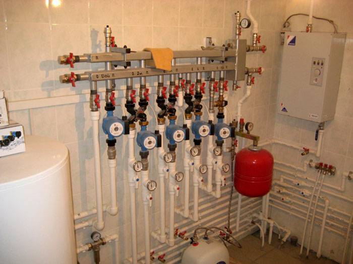
The use of a water gun with solid fuel equipment
When using a solid fuel unit, the hydraulic separator is connected at the entry - exit point. This option for connecting a different type of heating device ensures the selection of the optimal and individual temperature regime for all components separately.
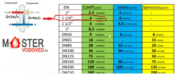
Today, consumers, having figured out how the hydraulic arrow for heating works, prefer ready-made products that are on sale. Choose a hydraulic separator from the catalog, based on the power of the unit and the maximum water flow.
Diy thermal separator
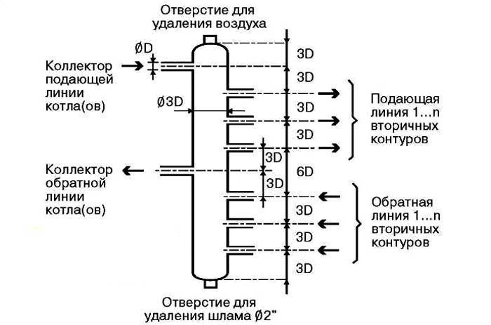
The design of the hydraulic arrow is so simple that it allows the owner of a country house to assemble it on his own without much difficulty. An important manufacturing stage is the correct calculation of the diameters of the branch pipes and the separator. The simple design of the unit follows the 3-diameter rule.

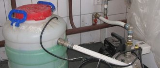
It is possible to make a water gun with your own hands.
In this case, the diameter of the nozzle is taken as a basis, which is the same for all inlet and outlet circuits. The total diameter of the hydraulic arrow will be equal to 3 diameters of the branch pipe, and its length should be 4 diameters of the separator. The axes of the inlet and outlet pipelines will be located from the ends of the structure at a distance of one diameter of the thermal separator.
This size ratio allows you to extinguish the speed of movement of the coolant to the desired results. In the future, you only need to select pipes of suitable sizes and carry out welding work. Such a simple design will work successfully in small heating systems.
The principle of operation of the hydraulic arrow:
What do you need to know?
The hydraulic arrow is an additional unit, which is located in a vertical position. It is made in the form of a cylinder, but it can also have a section in the form of a rectangle. Nozzles are cut into this device, which are suitable for the boiler, as well as for the heat exchange circuits. In this device, the division of a small circuit, as well as extended heating circuits, is carried out. Traditional low loss header designs are often used.
Device diagram
Such a device maintains thermal and hydraulic balance. With its help, it is possible to achieve low pressure losses, as well as heat energy and productivity. The design allows to increase the efficiency of the heating system and reduce the resistance in the system.
The important characteristics include indicators of the diameters of the pipes and the main device. The rest of the parameters can be found from the standard schemes.
Built-in hydraulic catcher
The program has some nuances:
in the calculations, the power of the heating equipment is necessarily used
To determine this indicator, you can also use a special calculation program; an important characteristic is the speed of movement of the coolant in the vertical direction. The lower this indicator, the better the coolant will get rid of gases and sludge.
Also, in this case, a smoother mixing of the cooled and hot streams will occur. The most optimal option is 0.1-0.2 m / s. You can select the required parameter in the program; a special characteristic is the operating mode of the entire structure. This takes into account the temperature levels in the line passing from the heater. All indicators are entered into the calculator.
A special calculation formula is provided in the applied calculation algorithm.As a result, the result will be shown, which will show the suitable diameter for the hydraulic arrow, as well as the section of the pipes used. The rest of the parameters of the linear type are even easier to determine.
Before proceeding with the installation of such a device, it is worthwhile to study all the functions of the hydraulic arrow.
Related article:
Save time: select articles by mail every week
Calculation of the hydraulic arrow: device and installation
Experts suggest installing a pressure gauge and a thermometer on the hydraulic arrow. These devices can be sold complete with a hydraulic arrow, of course, significantly affecting the cost. But the presence of these devices is not a prerequisite at all. If required, it is possible to buy them later and install them anywhere in the system, not just on the hydraulic arrow.
The hydraulic arrow can be installed not only vertically, but also horizontally. It is even possible to install it obliquely. The hydraulic arrow will work properly in any position.
The main thing is that the automatic air vent, which is placed at the highest point, looks upward (vertically) with its cap. There is a shut-off valve under the air vent. If it becomes necessary to change the air vent, the valve will allow you to do this without stopping the system. At the lowest point, a drain valve is installed, with the help of which any debris (rust, sludge) formed in the coolant and settled in the form of sediment in the sump is removed. The tap is opened from time to time and this dirt is simply drained into any container. The hydraulic boom has many functions in the system.
You can make the calculation of the hydraulic arrow on paper by hand
List of functions performed by the hydraulic arrow:
- System balancing;
- Pressure stabilization;
- Sump function;
- Removing air from the coolant;
- Reducing the load on equipment and boiler;
- Prevention of temperature surges.
The functions listed above allow you to prevent premature wear of the heating system, avoid serious damage to boilers and equipment, and protect parts made of metal from oxidation.
Popular manufacturers
There are not so few companies engaged in the production of hydraulic dividers for heating networks as it might seem at first glance. However, today we will get acquainted with the products of only two companies, GIDRUSS and Atom LLC, as they are considered the most popular.
Table. Characteristics of the low loss header manufactured by GIDRUSS.
| Model, illustration | Main characteristics |
| 1.GR-40-20 | - the product is made of structural steel; - designed for one consumer; - the minimum power of the heater is 1 kilowatt; - its maximum power is 40 kilowatts. |
| 2. GR-60-25 | - the product is made of structural steel; - designed for one consumer; - the minimum power of the heater is 10 kilowatts; - its maximum power is 60 kilowatts. |
| 3. GR-100-32 | - the product is made of structural steel; - designed for one consumer; - the minimum power of the heater is 41 kilowatts; - its maximum power is 100 kilowatts. |
| 4. GR-150-40 | - the product is made of structural steel; - designed for one consumer; - the minimum power of the heater is 61 kilowatts; - its maximum power is 150 kilowatts. |
| 5. GR-250-50 | - the product is made of structural steel; - designed for one consumer; - the minimum power of the heater is 101 kilowatts; - its maximum power is 250 kilowatts. |
| 6.GR-300-65 | - the product is made of structural steel; - designed for one consumer; - the minimum power of the heater is 151 kilowatts; - its maximum power is 300 kilowatts. |
| 7. GR-400-65 | - the product is made of structural steel; - designed for one consumer; - the minimum power of the heater is 151 kilowatts; - its maximum power is 400 kilowatts. |
| 8. GR-600-80 | - the product is made of structural steel; - designed for one consumer; - the minimum power of the heater is 251 kilowatts; - its maximum capacity is 600 kilowatts. |
| 9.GR-1000-100 | - the product is made of structural steel; - designed for one consumer; - the minimum power of the heater is 401 kilowatts; - its maximum capacity is 1000 kilowatts. |
| 10. GR-2000-150 | - the product is made of structural steel; - designed for one consumer; - the minimum power of the heater is 601 kilowatts; - its maximum capacity is 2000 kilowatts. |
| 11. GRSS-40-20 | - the product is made of stainless steel AISI 304; - designed for one consumer; - the minimum power of the heater is 1 kilowatt; - its maximum power is 40 kilowatts. |
| 12. GRSS-60-25 | - the product is made of stainless steel AISI 304; - designed for one consumer; - the minimum power of the heater is 11 kilowatts; - its maximum power is 60 kilowatts. |
| 13. GRSS-100-32 | - the product is made of stainless steel AISI 304; - designed for one consumer; - the minimum power of the heater is 41 kilowatts; - its maximum power is 100 kilowatts. |
Note also that each of those listed above for heating also performs the functions of a kind of sump. The working fluid in these devices is cleaned of all sorts of mechanical impurities, thereby significantly increasing the operational life of all moving components of the heating system.
The role of the hydraulic arrow in modern heating systems
In order to find out what a hydraulic arrow is and what functions it performs, first we will get acquainted with the peculiarities of the operation of individual heating systems.
Simple option
The simplest version of a heating system equipped with a circulation pump will look something like this.
Of course, this diagram has been greatly simplified, since many network elements in it (for example, a security group) are simply not shown in order to "make it easier" to understand the picture. So, in the diagram, you can see, first of all, a heating boiler, thanks to which the working fluid is heated. A circulation pump is also visible, through which the liquid moves along the supply (red) pipeline and the so-called "return". What is characteristic, such a pump can be installed both in the pipeline and directly in the boiler (the latter option is more inherent in wall-mounted devices).
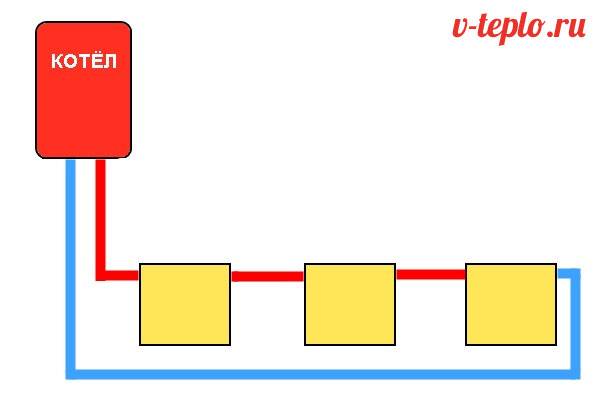
Note! Even in a closed loop, there are heating radiators, thanks to which heat exchange is carried out, that is, the generated heat is transferred to the room. If the pump is correctly selected in terms of pressure and performance, then it alone will be quite enough for a single-circuit system, therefore, there is no need to use other auxiliary devices
If the pump is correctly selected in terms of pressure and performance, then it alone will be quite enough for a single-circuit system, therefore, there is no need to use other auxiliary devices.
More complex option
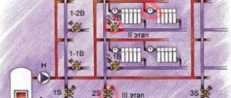
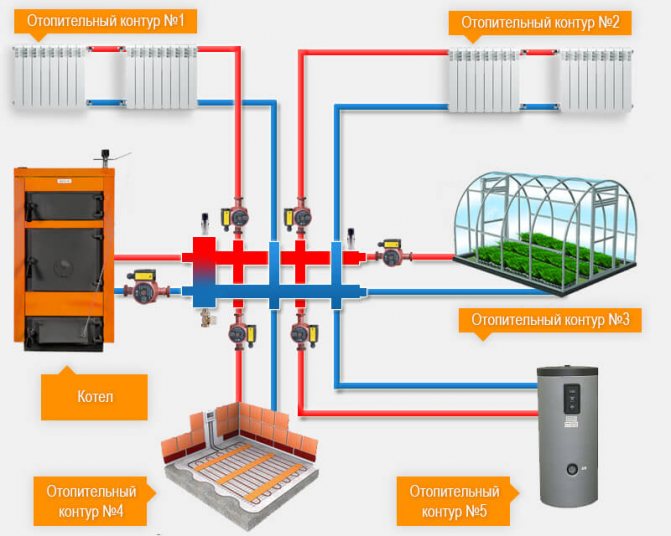
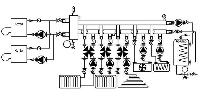
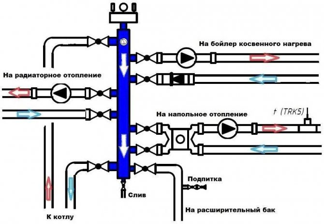
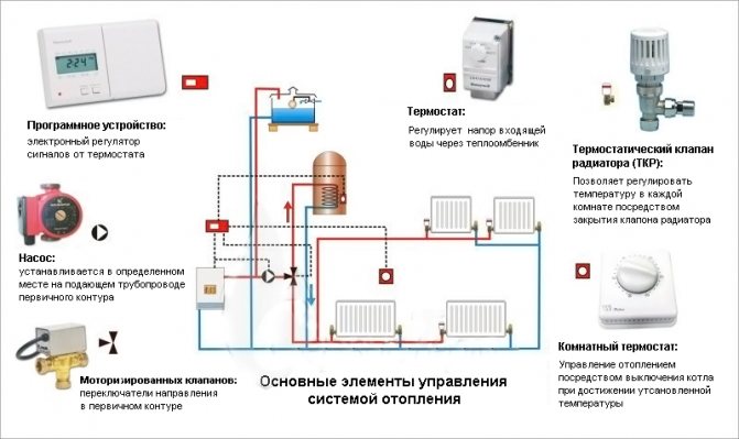
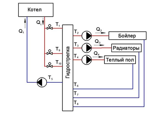
If the area of the house is large enough, then the scheme presented above will not be enough for it. In such cases, several heating circuits are used at once, so the diagram will look somewhat different.
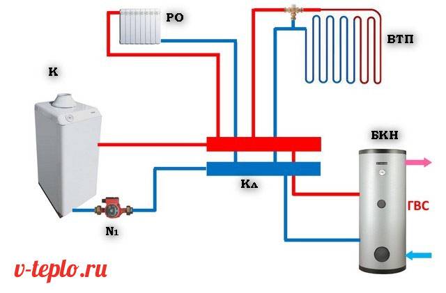
Here we see that, through the pump, the working fluid enters the collector, and from there it is already transferred to several heating circuits.The latter include the following elements.
- High temperature circuit (or several), in which there are collectors or conventional batteries.
- DHW systems equipped with an indirect boiler. The requirements for the movement of the working fluid are special here, since the temperature of heating the water in most cases is regulated by changing the flow rate of the fluid passing through the boiler.
- Warm floor. Yes, the temperature of the working fluid for them should be an order of magnitude lower, which is why special thermostatic devices are used. Moreover, the contours of the underfloor heating have a length that significantly exceeds the standard wiring.
It is quite obvious that one circulation pump cannot cope with such loads. Of course, today high-performance models of increased power are being sold, capable of creating a sufficiently high pressure, but it is worth thinking about the heating device itself - its capabilities, alas, are not limitless. The fact is that the elements of the boiler are initially intended for certain indicators of pressure and productivity. And these indicators should not be exceeded, since this is fraught with breakdown of an expensive heating system.
In addition, the circulation pump itself, operating at the limit of its own capabilities in order to provide all the circuits of the network with liquid, will not be able to serve for a long time. What can we say about the strong noise and consumption of electrical energy. But let's return to the topic of our article - to the water gun for heating.
Modes of operation
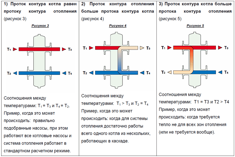
When talking about a hydraulic switch, they often draw an analogy with a railway switch. Their work is, indeed, similar: both devices set the desired direction of movement, in one case - transport, in the other - the coolant. The difference is that the “switching” of the hydraulic arrow does not require any external force, but occurs by itself, depending on the consumption of heat and hot water. The operating modes of the low loss header are discussed below.
Mode 1.
The load on the heating system is such that the primary and secondary flows coincide, i.e. the heat carrier heated by the boiler is completely transferred to consumers, and it is sufficient (
G
1 =
G
11 =
G
2 =
G
21,
T
1 =
T
11,
T
21 =
T
2). In this case, the hydraulic arrow is "switched on" directly and works as two separate pipelines. The movement diagram, chromograms of the velocities and pressures of the coolant in the separator body are shown for this mode on
fig. 2
... This mode can be called calculated.

Fig. 2.
Mode 2.
The heating system is loaded. The total consumption of consumers exceeds the consumption in the heat source circuit (
G
1 <
G
11,
T
1 >
T
11;
T
21 =
T
2;
G
1 =
G
2;
G
11 =
G
21). The difference in flow rates is compensated by mixing a part of the coolant from its "return" (
fig. 3
). The mode is described by the following formulas: Δ
T
1 =
T
1 –
T
2 =
Q
/
c
·
G
1, Δ
T
2 =
T
11 –
T
21 =
Q
/
c
·
G
11,
T
2 =
T
1 - Δ
T
1,
T
11 =
T
21 + Δ
T
2.
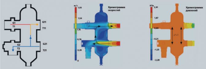
Fig. 3.
Mode 3.
Heat consumption is reduced (for example, in the off-season), and the coolant flow in the secondary circuit is less than in the primary one (
G
1 >
G
11,
T
1 =
T
11,
T
21 ˂
T
2,
G
1 =
G
2,
G
11 =
G
21). In this case, the excess coolant returns to the boiler through the hydraulic arrow, without getting into the secondary circuit (
fig. four
). Design formulas: Δ
T
1 =
T
1 –
T
2 =
Q
/
c
·
G
one; Δ
T
2 =
T
11 –
T
21 =
Q
/
c
·
G
11;
T
2 =
T
1 - Δ
T
1;
T
11 =
T
1;
T
21 =
T
11 - Δ
T
2. This mode is optimal when it is necessary to protect the boiler from the so-called low-temperature corrosion.

Fig. four.
In the absence of flows through the circuits of the heating system, the hydraulic separator does not interfere with the natural (due to gravitational forces) circulation of the coolant, which is demonstrated by the chromogram shown on fig. five
.
Fig. 5. Chromogram of temperature in static mode
What is a hydrostatic gun for: principle of operation, purpose and calculations
Many heating systems in private households are unbalanced.The hydraulic arrow allows you to separate the heating unit circuit and the secondary heating system circuit. This improves the quality and reliability of the system.
Features of the device
When choosing a water gun, you need to carefully study the principle of operation, purpose and calculations, as well as find out the advantages of the device:
- a separator is required to ensure that technical specifications are met;
- the device maintains temperature and hydraulic balance;
- parallel connection ensures minimal losses of heat energy, productivity and pressure;
- protects the boiler from thermal shock, and also evens out the circulation in the circuits;
- allows you to save fuel and electricity;
- a constant volume of water is maintained;
- reduces hydraulic resistance.
Function of the device with a four-way mixer
The peculiarities of the operation of the hydraulic arrow allow to normalize the hydrodynamic processes in the system.
Helpful information! Timely elimination of impurities allows you to extend the service life of meters, heating devices and valves.
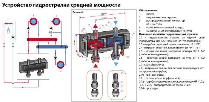
Heating water arrow device
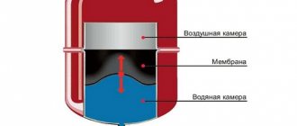
Before buying a water gun for heating, you need to understand the structure of the structure.
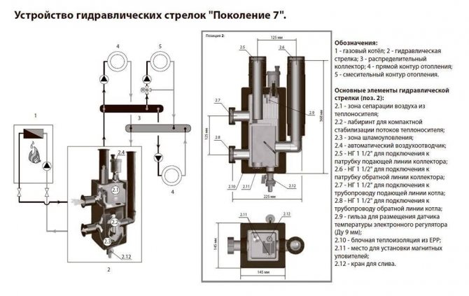
Internal structure of modern equipment
The hydraulic separator is a vertical vessel made of large-diameter pipes with special plugs at the ends. The dimensions of the structure depend on the length and volume of the circuits, as well as on the power. In this case, the metal case is installed on support posts, and small products are attached to brackets.
The connection to the heating pipe is made with threads and flanges. Stainless steel, copper or polypropylene are used as the material for the hydraulic arrow. In this case, the body is treated with an anti-corrosion agent.
Note! Polymer products are used in a system with a 14-35 kW boiler. Making such a device with your own hands requires professional skills.
Additional equipment functions
The principle of operation, purpose and calculations of the hydraulic arrow can be found out and performed independently. The new models have the functions of a separator, separator and temperature controller. The thermostatic expansion valve provides a temperature gradient for the secondary circuits. The elimination of oxygen from the coolant reduces the risk of erosion of the internal surfaces of the equipment. Removing excess particles increases impeller life.
There are perforated partitions inside the device that divide the internal volume in half. This does not create additional resistance.
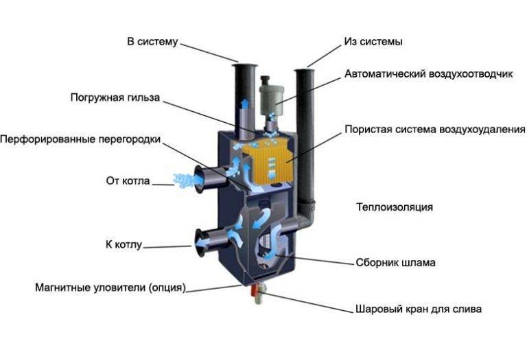
The diagram shows the device in section
Helpful information! Sophisticated equipment requires a temperature gauge, pressure gauge, and power line for the system.
The principle of operation of a hydraulic arrow in heating systems
The choice of a hydraulic arrow depends on the speed of the coolant. In this case, the buffer zone separates the heating circuit and the heating boiler.
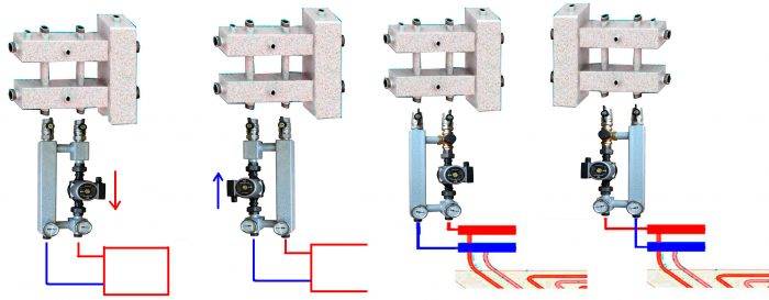
There are the following schemes for connecting a hydraulic arrow:
neutral scheme of work, in which all parameters correspond to the calculated values. At the same time, the structure has a sufficient total power;
Using the underfloor heating contour
a certain scheme is applied if the boiler does not have sufficient power. If there is a lack of flow, an admixture of the cooled heat carrier is required. When there is a temperature difference, temperature sensors are triggered;
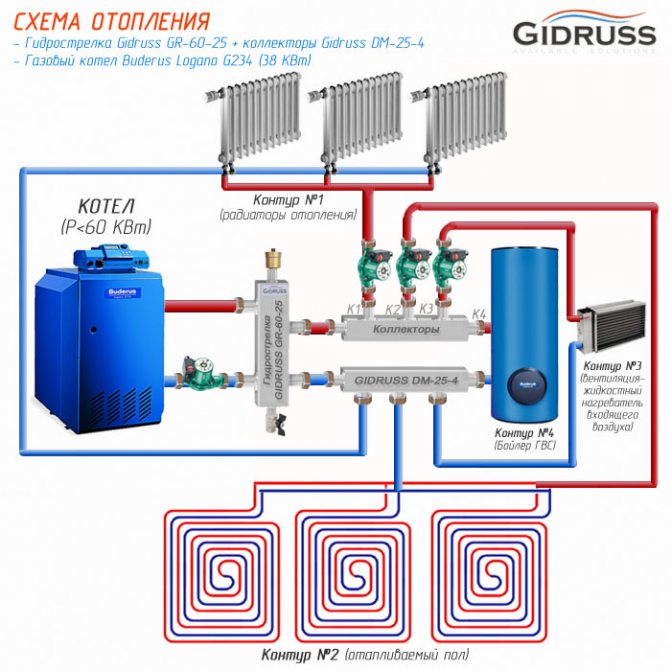
Heating system diagram
the volume of flow in the primary circuit is greater than the consumption of the coolant in the secondary circuit. At the same time, the heating unit operates optimally. When the pumps in the second circuit are turned off, the coolant moves through the hydraulic arrow along the first circuit.
Use of a hydrostatic arrow
The capacity of the circulation pump must be 10% more than the head of the pumps in the second circuit.
Features of the system
This table shows some of the models and their prices.
Calculation of the diameter of the hydraulic arrow
If you think that only a specialist with a technical education can understand the device of a hydraulic arrow, then you are mistaken. In this article, we will explain in an accessible form the purpose of the hydraulic arrow, the basic principles of its functioning and rational calculation methods.
Definition
Let's start with the terminology. Hydrostrel (synonyms: hydrodynamic thermal separator, low loss header) is a device designed to equalize both temperature and pressure in the heating system.
Main functions
The hydrodynamic thermal separator is designed for:
- increasing energy efficiency by increasing the efficiency of the boiler, pumps, which leads to a decrease in fuel costs;
- ensuring the stable operation of the system;
- elimination of the hydrodynamic effect of some circuits on the total energy balance of the entire heating system (to separate the radiator heating circuit and hot water supply).
What are the forms of a water arrow?
A hydrodynamic thermal separator is a vertical volumetric container, which in cross-section can be in the form of a circle or a square.
Taking into account the theory of hydraulics, the round shaped hydraulic arrow functions better than its square counterpart. Nevertheless, the second option fits better into the interior.
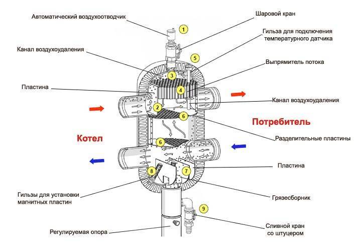
Features of functioning
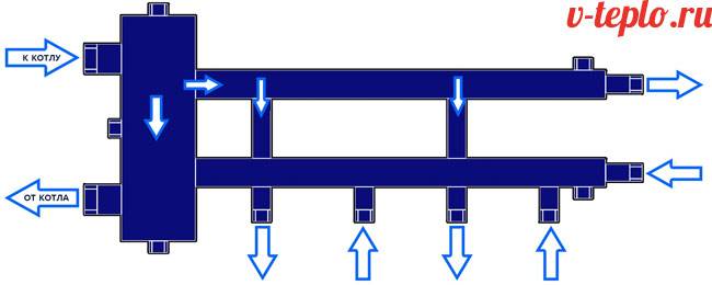
Before exploring the principle of operation of the hydraulic arrow, take a look at the diagram below.
Pumps Н1 and Н2 create flow rates Q1 and Q2, respectively, in the primary and secondary circuits. Thanks to the operation of the pumps, the coolant circulates in the circuits and is mixed in the hydraulic arrow.
Variant 1. If Q1 = Q2, then the coolant moves from one circuit to the second.
Variant 2. If Q1> Q2, then the coolant moves in the hydraulic arrow from top to bottom.
Option 3. If Q1
Thus, a hydrodynamic thermal separator is needed in the case when there is a heating system of complex design, consisting of many circuits.
A little about numbers ...
There are several methods by which it is carried out calculation of a hydraulic arrow.
The diameter of the low loss header is determined by the following formula:
where D is the diameter of the water gun, Q is the water flow rate (m3 / s (Q1-Q2), π is a constant equal to 3.14, and V is the vertical flow rate (m / s). It should be noted that the economically advantageous speed is 0 , 1 m / s.
The numerical values of the diameters of the nozzles included in the hydraulic arrow are also calculated using the above formula. The difference is that the speed in this case is 0.7-1.2 m / s, and the flow rate (Q) is calculated for each carrier separately.
The volume of the hydraulic arrow affects the quality of the system and helps to regulate temperature fluctuations. The effective volume is 10-30 liters.
To determine the optimal dimensions of the hydrodynamic thermal separator, the method of three diameters and alternating nozzles is used
The calculation is carried out according to the formula
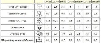
| Boiler power | DN pipes from the boiler | DN pipe under the arrow |
| 70 kWt | 32 | 100 |
| 40 kWt | 25 | 80 |
| 26 kWt | 20 | 65 |
| 15 kWt | 15 | 50 |
where π is a constant equal to 3.14, W is the speed with which the coolant moves in the hydraulic gun (m / s), Q is the water flow rate (m3 / s (Q1-Q2), 1000 is the conversion of a meter to millimeters).
Only pluses and no minuses!
Based on the foregoing, the following advantages of using hydraulic switches can be distinguished:
- optimization of work and increase in the service life of boiler equipment;
- system stability;
- simplification of the selection of pumps;
- the ability to control the temperature gradient;
- if necessary, you can change the temperature in any of the circuits;
- ease of use;
- high economic efficiency.
Calculation method
To make a hydrostatic arrow for heating with your own hands, you will need preliminary calculations. This figure shows the principle by which the dimensions of the device can be calculated quickly, with a sufficiently high accuracy.
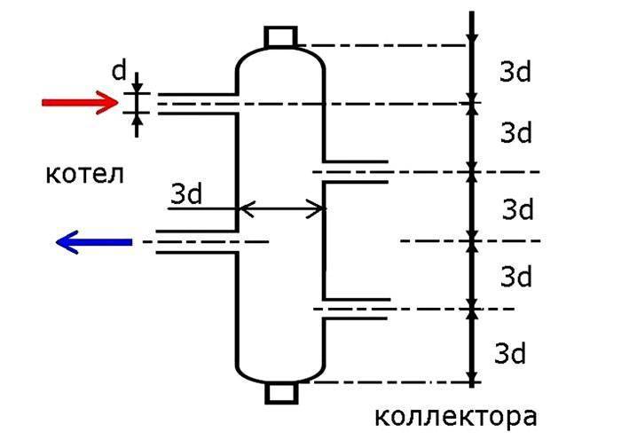
Principle "3d"
These proportions were obtained taking into account the results of experiments, the efficiency of the device in different modes. The value of D, which consists of three d's, can be calculated using the following formula:

- РВ - water consumption in cubic meters;
- SP is the water flow rate in m / s.
In order to fulfill the above-mentioned optimal conditions, the value of SP = 0.1 is inserted into the formula. The flow rate in this device is calculated from the difference Q1-Q2. Without measurements, these values can be found out using data from the technical data sheets of the circulation pumps of each circuit.
Calculator for calculating the parameters of the hydraulic arrow based on the performance of the pumps
Dignity
Such delimiters are a necessary and useful mechanism that has many advantages:
- there is no problem with finding the values of the pumping device;
- there is no influence on each other of the boiler and heating circuits;
- the consumer and the heat generator are loaded only from their own water flow;
- there are additional connection points (for example: an expansion tank or an air vent).
A heat generator on a hydraulic switch will create a comfortable temperature with low energy costs. With the correct design of such a technology, you will save about 20% on gas and up to 55% on electricity.
Hydraulic switch devices are now quite widely used. They are selected according to special catalogs, while the flow of water and power are determined.
Ready-made hydroarms are treated with a special mixture that prevents corrosion and already has waterproofing. So, if problems arise, it is easier to contact and purchase the necessary hydraulic arrow. This will save a lot of money and time.
Watch a video in which a specialist explains in detail the features of calculating a hydraulic arrow for heating:
Source: teplo.guru
The hydraulic separator or, in other words, the hydraulic arrow of the heating system is a simple design, but the most important in functionality element that ensures smooth and easily adjustable operation of all devices and circuits. It acquires particular importance in the presence of several heat sources (boilers or other installations), independent circuits from each other, including hot water supply fed through an indirect heating boiler.
Calculator for calculating the parameters of the hydraulic arrow based on the performance of the pumps
The low loss header can be purchased ready-made or made in-house. In any case, you need to know its linear parameters. One of the ways to calculate them is an algorithm based on the performance of the circulating pumps involved in the system. The formula is rather cumbersome, so it is better to use a special calculator for calculating the parameters of a hydraulic arrow based on the performance of the pumps, which is located below.
In the final section of the publication, the corresponding explanations for carrying out the calculations are given.
Calculator for calculating the parameters of the hydraulic arrow based on the performance of the pumps
Specify the requested data and press the button "Calculate the parameters of the hydraulic arrow" Specify the expected speed of the vertical movement of the coolant in the hydraulic arrow 0.1 m / s 0.15 m / s 0.2 m / s million Specify a convenient unit for measuring the pump performance m? per hour liters per minute Specify in sequence the capacity of all pumps in the heating and hot water circuits. Indicate with a number in the units of measure that were selected above. A period is used as the decimal separator.If there is no pump, leave the field blank. Pump # 1 Pump # 2 Pump # 3 Pump # 4 Pump # 5 Pump # 6 Specify the capacity of the pump (pumps) in the small circuit of the boiler (s) Boiler pump # 1 Boiler pump # 2
Manufacturers and prices
It will be easier to buy a water gun for heating after reading the data from the following table. Current price offers can be clarified immediately before purchasing the goods. But this information is useful for comparative analysis, taking into account different characteristics of products.
Table 1. Characteristics and average cost of hydraulic shooters
| Picture | Equipment model | Heating system power in kW (maximum) | Price in rub. | Notes (edit) |
| GR-40-20, Gidruss (Russia) | 40 | 3 600 — 3 800 | The cube body is made of carbon steel with anti-corrosion coating, the simplest model. | |
| GRSS-60-25, Gidruss (Russia) | 60 | 9 800 — 10 600 | Stainless steel body, six nozzles, integrated separation mesh and a set of mounting brackets as standard. | |
| TGR-60-25х5, Gidruss (Russia) | 60 | 10 300 — 11 800 | Low-alloy steel body, the ability to connect up to 4 external circuits + heating. | |
| GRSS-150-40, Gidruss (Russia) | 150 | 15 100 — 16 400 | Stainless steel, 6 spigots. | |
| MH50, Meibes (Germany) | 135 | 54 600 — 56 200 | Sophisticated design with integrated sludge and air removal devices. |
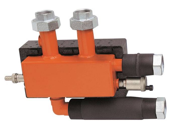
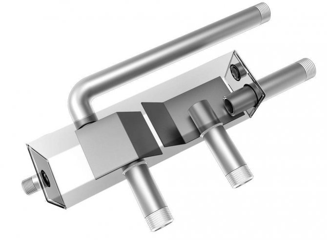
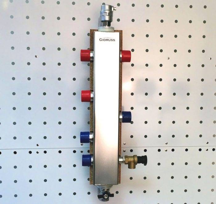
Modern hydraulic arrow
It is clear from the table that, in addition to general technical parameters, the following factors affect the cost:
- body material;
- the ability to connect additional circuits;
- the complexity of the design;
- availability of additional equipment;
- manufacturer's name.
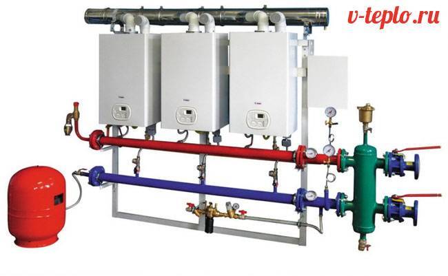
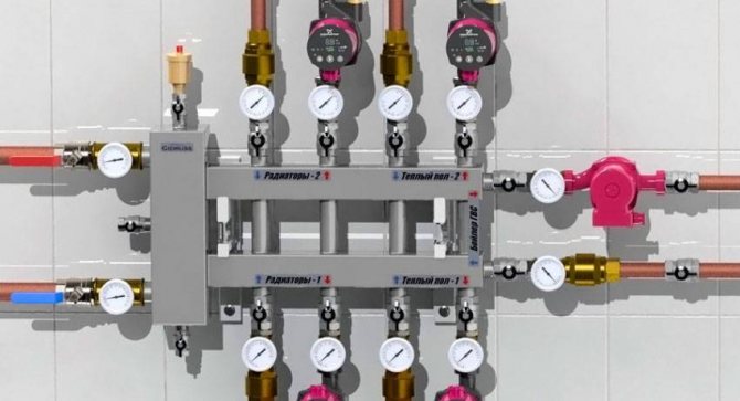
The use of a hydraulic arrow together with a manifold and the solution of other tasks
Installation of a hydraulic arrow in a connection diagram with several heating interconnections is carried out using a special switchgear. The manifold consists of two separate parts with nozzles. Shut-off valves, measuring and other devices are connected to them.
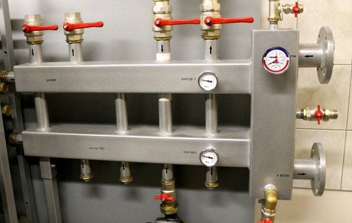
Hydrostrel in a single block with a manifold
To connect solid fuel boilers, it is recommended to increase the volume of the hydraulic expansion joint. This will create a protective barrier to prevent a sudden rise in temperature in the system. Such jumps in parameters are typical for aging equipment.
In the presence of a shift in the outlet nozzles along the height, the movement of the liquid slows down somewhat, and the path increases. Such a modernization in the upper part improves the separation of gas bubbles, and in the lower part it is useful for collecting debris.
Connection of several different consumers
This connection of several circuits provides different temperature levels. But one must understand that it is impossible to obtain the exact values of the distribution of heat in dynamics. For example, the approximate equality of the consumption values Q1 and Q2 will lead to the fact that the temperature difference in the circuits of radiators and underfloor heating will be insignificant.
Conclusions and recommendations
To make a hydro arrow from polypropylene with your own hands, you will need a special soldering iron. Working with metals will require welding equipment and related skills. Despite the large number of instructions on the Internet, it will be difficult to make quality products. Taking into account all the costs and difficulties, it is more profitable to purchase a ready-made device in a store.
With the help of knowledge about hydraulic arrows, principles of operation, purpose and calculations, a specific model is selected. They take into account the peculiarities of boilers and heat consumers.
To create complex systems, you can turn to specialized specialists for help.
Save time: select articles by mail every week
Purpose and principle of operation
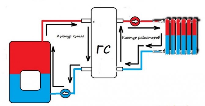
The hydraulic arrow (hydraulic arrow, hydraulic divider) serves to separate and link the primary and secondary circuits of the heating system.In this case, a secondary circuit is understood as a set of heat consumer circuits - floor heating loops, radiator heating, hot water supply. Since the load on these subsystems is not constant, the thermohydraulic parameters (temperature, flow rate, pressure) of the secondary circuit as a whole are also variable. At the same time, stability of these characteristics is desirable for normal operation of the heat source (heating boiler). The hydraulic switch installed between the boiler and consumers (fig. one
).

Fig. 1. Hydraulic arrow in the heating system
The action of the hydraulic separator is based on a significant increase in the flow cross section of the coolant: as a rule, the hydraulic arrow is performed in such a way that the diameter of its body (flask) is three times the diameter of the largest connecting pipe or so that the cross section of the body is equal to the total section of all pipes.
With a threefold increase in the diameter of the flow, its velocity decreases by nine, and the dynamic pressure - by 81 times (both there and there - a quadratic dependence). This allows us to assert that the pressure drops between the pipelines connected to the hydraulic switch are negligible.
What is a water gun for heating
In complex branched heating systems, even oversized pumps will not be able to meet different parameters and operating conditions of the system. This will negatively affect the functioning of the boiler and the service life of expensive equipment. In addition, each of the connected circuits has its own head and capacity. This leads to the fact that at the same time the entire system cannot work smoothly.
Even if each circuit is equipped with its own circulation pump, which will meet the parameters of a given line, the problem will only worsen. The entire system will become unbalanced because the parameters of each circuit will differ significantly.
To solve the problem, the boiler must deliver the required volume of coolant, and each circuit must take from the collector exactly as much as needed. In this case, the manifold acts as a hydraulic separator. It is in order to isolate the "small boiler" flow from the general circuit that a hydraulic separator is needed. Its second name is a hydraulic arrow (HS) or a hydraulic arrow.
The device received this name because, like a railway switch, it can separate the coolant flows and direct them to the desired circuit. This is a rectangular or round tank with end caps. It connects to the boiler and manifold and has several cut-in pipes.
The principle of operation of the low loss header
The coolant flow passes the hydraulic separator for heating at a speed of 0.1-0.2 meters per second, and the boiler pump accelerates the water to 0.7-0.9 meters. The speed of the water flow is damped by changing the direction of movement and the volume of the passing liquid. In this case, the heat loss in the system will be minimal.
The principle of operation of the hydraulic switch is that the laminar movement of the water flow practically does not cause hydraulic resistance inside the body. This helps to maintain the flow rate and reduce heat loss. This buffer zone separates the consumer chain and the boiler. This contributes to the autonomous operation of each pump without disturbing the hydraulic balance.
Modes of operation
The hydraulic arrow for heating systems has 3 operating modes:
- In the first mode, the hydraulic separator in the heating system creates equilibrium conditions. That is, the flow rate of the boiler circuit does not differ from the total flow rate of all circuits that are connected to the hydraulic switch and the collector. In this case, the coolant does not stay in the device and moves horizontally through it. The temperature of the heat carrier at the supply and discharge nozzles is the same.This is a rather rare mode of operation in which the hydraulic arrow does not affect the operation of the system.
- Sometimes there is a situation when the flow rate on all circuits exceeds the boiler capacity. This happens at the maximum flow rate of all circuits at once. That is, the demand for the heat carrier has exceeded the capabilities of the boiler circuit. This will not lead to a stop or imbalance of the system, because a vertical upward flow will form in the hydraulic gun, which will provide a mixture of hot coolant from a small circuit.
- In the third mode, the heating arrow works most often. In this case, the flow rate of the heated liquid in the small circuit is higher than the total flow rate at the manifold. That is, demand in all circuits is lower than supply. This also will not lead to an imbalance in the system, because a vertical downward flow is formed in the device, which will ensure that the excess volume of liquid is discharged into the return.
Additional features of the hydraulic arrow
The principle of operation of the low loss header in the heating system described above allows the device to realize other possibilities:
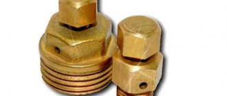
After entering the body of the separator, the flow rate decreases, this leads to the settling of insoluble impurities contained in the coolant. To drain the accumulated sediment, a valve is installed in the lower part of the hydraulic arrow. By reducing the speed of the ceiling, gas bubbles are released from the liquid, which are discharged from the device through an automatic air vent installed in the top. In fact, it acts as an additional separator in the system
It is especially important to remove gas at the outlet of the boiler, because when the liquid is heated to high temperatures, gas formation increases. The hydraulic separator is very important in cast iron boiler systems. If such a boiler is connected directly to the collector, then the ingress of cold water into the heat exchanger will lead to the formation of cracks and equipment failure.


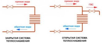
Thermal diagrams of boiler rooms with hot water boilers for closed heat supply systems
Thermal diagrams of boiler rooms with hot water boilers for closed heat supply systems
The choice of a heat supply system (open or closed) is made on the basis of technical and economic calculations. Using the data received from the customer and the methodology described in § 5.1, they begin to draw up, then calculate the schemes, which are called thermal schemes of boiler rooms with hot water boilers for closed heat supply systems, since the maximum heating capacity of cast iron boilers does not exceed 1.0 - 1, 5 Gcal / h.
Since it is more convenient to consider thermal schemes using practical examples, below are the basic and detailed schemes of boiler houses with hot water boilers. The basic thermal diagrams of boiler houses with hot water boilers for closed heat supply systems operating on a closed heat supply system are shown in Fig. 5.7.
Fig. 5.7. Basic thermal diagrams of boiler rooms with hot water boilers for closed heat supply systems.
1 - hot water boiler; 2 - network pump; 3 - recirculation pump; 4 - raw water pump; 5 - make-up water pump; 6 - make-up water tank; 7 - raw water heater; 8 - heater for chemically treated water; 9 - make-up water cooler; 10 - deaerator; 11 - vapor cooler.
Water from the return line of heating networks with a low pressure (20 - 40 m of water column) is supplied to the network pumps 2. There is also supplied water from the make-up pumps 5, which compensates for water leaks in the heating networks. Hot network water is also supplied to pumps 1 and 2, the heat of which is partially used in heat exchangers for heating chemically treated 8 and raw water 7.
To ensure the temperature of the water in front of the boilers, set according to the conditions for preventing corrosion, the required amount of hot water from the boilers 1 is fed into the pipeline behind the network pump 2.The line through which hot water is supplied is called recirculation. Water is supplied by a recirculation pump 3, which pumps over heated water. In all operating modes of the heating network, except for the maximum winter one, part of the water from the return line after the network pumps 2, bypassing the boilers, is fed through the bypass line in the amount of G per to the supply line, where water, mixing with hot water from the boilers, provides the specified design temperature in the supply line of heating networks. The addition of chemically treated water is heated in heat exchangers 9, 8 11 is deaerated in a deaerator 10. Water for replenishing heating networks from tanks 6 is taken by a make-up pump 5 and fed into the return line.
Even in powerful hot water boilers operating on closed heat supply systems, you can get by with one make-up water deaerator with low performance. The power of the make-up pumps and the equipment of the water treatment plant are also decreasing and the requirements for the quality of the make-up water are reduced in comparison with boiler houses for open systems. The disadvantage of closed systems is a slight increase in the cost of equipment for subscriber hot water supply units.
To reduce the consumption of water for recirculation, its temperature at the outlet of the boilers is maintained, as a rule, above the temperature of the water in the supply line of heating networks. Only at the calculated maximum winter mode, the water temperatures at the outlet from the boilers and in the supply line of the heating networks will be the same. To ensure the design temperature of the water at the inlet to the heating networks, network water from the return pipeline is added to the water leaving the boilers. To do this, a bypass line is installed between the return and supply pipelines, after the network pumps.
The presence of mixing and recirculation of water leads to the operating modes of steel hot water boilers, which differ from the mode of heating networks. Hot water boilers work reliably only if the amount of water passing through them is maintained constant. Water flow must be maintained within specified limits, regardless of fluctuations in thermal loads. Therefore, the regulation of the supply of heat energy to the network must be carried out by changing the temperature of the water at the outlet from the boilers.
To reduce the intensity of external corrosion of pipes of the surfaces of steel hot water boilers, it is necessary to maintain the water temperature at the inlet to the boilers above the dew point temperature of flue gases. The minimum permissible water temperature at the inlet to the boilers is recommended as follows:
- when working on natural gas - not lower than 60 ° С;
- when operating on low-sulfur fuel oil - not lower than 70 ° С;
- when operating on high-sulfur fuel oil - not lower than 110 ° С.
Due to the fact that the water temperature in the return lines of heating networks is almost always below 60 ° C, the thermal schemes of boiler houses with hot water boilers for closed heat supply systems provide, as noted earlier, recirculating pumps and corresponding pipelines. To determine the required water temperature behind steel hot water boilers, the operating modes of heating networks must be known, which differ from the schedules or regime boiler units.
In many cases, water heating networks are designed to operate according to the so-called heating temperature schedule of the type shown in fig. 2.9. The calculation shows that the maximum hourly flow rate of water entering the heating networks from the boilers is obtained when the mode corresponds to the break point of the water temperature graph in the networks, that is, at the outside air temperature, which corresponds to the lowest water temperature in the supply line. This temperature is kept constant even if the outside temperature rises further.
Based on the foregoing, the fifth characteristic mode is introduced into the calculation of the heating scheme of the boiler house, which corresponds to the break point of the water temperature graph in the networks.Such graphs are built for each area with the corresponding calculated outdoor air temperature according to the type shown in Fig. 2.9. With the help of such a graph, the required temperatures in the supply and return lines of heating networks and the required water temperatures at the outlet of the boilers are easily found. Similar graphs for determining water temperatures in heating networks for various design temperatures of the outside air - from -13 ° С to - 40 ° С were developed by Teploelektroproekt.
The temperature of the water in the supply and return lines, ° С, of the heating network can be determined by the formulas:
where tvn is the air temperature inside the heated premises, ° С; tH - design temperature of the outside air for heating, ° С; t′H - time-varying outdoor air temperature, ° С; π′i - water temperature in the supply pipeline at tн ° С; π2 is the water temperature in the return pipeline at tn ° C; tn is the water temperature in the supply pipeline at t′n, ° C; ∆t - calculated temperature difference, ∆t = π1 - π2, ° С; θ = πз -π2 - calculated temperature difference in the local system, ° С; π3 = π1 + aπ2 / 1+ a is the calculated temperature of the water entering the heater, ° С; π′2 is the temperature of the water flowing into the return pipeline from the device at t'H, ° С; a - displacement coefficient equal to the ratio of the amount of return water sucked in by the elevator to the amount of heating water.
The complexity of the calculation formulas (5.40) and (5.41) for determining the water temperature in heating networks confirms the advisability of using graphs of the type shown in Fig. 2.9, built for an area with a design outside air temperature of 26 ° C. The graph shows that at outdoor air temperatures of 3 ° C and higher, until the end of the heating season, the water temperature in the supply pipe of heating networks is constant and equal to 70 ° C.
The initial data for calculating the heating schemes of boiler houses with steel hot water boilers for closed heat supply systems, as mentioned above, are the heat consumption for heating, ventilation and hot water supply, taking into account the heat losses in the boiler room, networks and the heat consumption for the auxiliary needs of the boiler room.
The ratio of heating and ventilation loads and loads of hot water supply is specified depending on the local operating conditions of consumers. The practice of operating heating boiler houses shows that the average hourly heat consumption per day for hot water supply is about 20% of the total heating capacity of the boiler house. Heat losses in external heating networks are recommended to be taken in the amount of up to 3% of the total heat consumption. The maximum hourly estimated consumption of thermal energy for auxiliary needs of a boiler house with hot water boilers with a closed heat supply system can be taken according to the recommendation [9] in the amount of up to 3% of the installed heating capacity of all boilers.
The total hourly consumption of water in the supply line of heating networks at the outlet of the boiler house is determined based on the temperature regime of operation of heating networks, and, in addition, depends on the leakage of water through non-density. Leakage from heating networks for closed heat supply systems should not exceed 0.25% of the volume of water in the pipes of heating networks.
It is allowed to take approximately the specific volume of water in local heating systems of buildings per 1 Gcal / h of the total estimated heat consumption for residential areas of 30 m3 and for industrial enterprises - 15 m3.
Taking into account the specific volume of water in pipelines of heating networks and heating installations, the total volume of water in a closed system can be taken approximately equal to 45 - 50 m3 for residential areas, for industrial enterprises - 25 - 35 MS per 1 Gcal / h of the total calculated heat consumption.
Fig. 5.8. Detailed thermal diagrams of boiler rooms with hot water boilers for closed heat supply systems.
1 - hot water boiler; 2 - recirculation pump; 3 - network pump; 4 - summer network pump; 5 - raw water pump; 6 - condensate pump; 7 - condensate tank; 8 - raw water heater; 9 - heater for chemically purified water; 10 - deaerator; 11 - vapor cooler.
Sometimes, to preliminary determine the amount of network water leaking from a closed system, this value is taken within the range of up to 2% of the water flow rate in the supply line. Based on the calculation of the basic thermal diagram and after the selection of the unit capacities of the main and auxiliary equipment of the boiler house, a complete detailed thermal diagram is drawn up. For each technological part of the boiler house, separate detailed schemes are usually drawn up, i.e. for the equipment of the boiler house itself, chemical water treatment and fuel oil facilities. A detailed thermal diagram of a boiler room with three hot water boilers KV -TS - 20 for a closed heat supply system is shown in Fig. 5.8.
In the upper right part of this diagram there are hot water boilers 1, and in the left - deaerators 10 below the boilers there are recirculating network pumps below, under the deaerators there are heat exchangers (heaters) 9, deaerated water tank 7, filler pumps 6, raw water pumps 5, drain tanks and a purge well. When performing detailed thermal diagrams of boiler rooms with hot water boilers, a general station or aggregate layout diagram of equipment is used (Figure 5.9).
The general station heat circuits of boiler rooms with hot water boilers for closed heat supply systems are characterized by the connection of network 2 and recirculation 3 pumps, in which water from the return line of heating networks can flow to any of the network pumps 2 and 4 connected to the main pipeline that supplies water to all boilers of the boiler room. Recirculation pumps 3 supply hot water from a common line downstream of the boilers also into a common line that feeds water to all hot water boilers.
With the aggregate layout diagram of the boiler room equipment shown in Fig. 5.10, for each boiler 1, mains 2 and recirculation pumps 3 are installed.
Fig 5.9 General station layout of boilers for network and recirculation pumps. 1 - hot water boiler, 2 - recirculation, 3 - mains pump, 4 - summer mains pump.
Fig. 5-10. Aggregate layout of boilers KV - GM - 100, network and recirculation pumps. 1 - hot water pump; 2 - network pump; 3 - recirculation pump.
Return water flows in parallel to all mains pumps, and the discharge line of each pump is connected to only one of the water heating boilers. Hot water is supplied to the recirculation pump from the pipeline behind each boiler before it is connected to the common falling main and is directed to the feed line of the same boiler unit. When assembling with the aggregate scheme, it is envisaged to install one for all hot water boilers. In Figure 5.10, make-up and hot water lines to the main pipelines and heat exchanger are not shown.
The aggregate method of placing equipment is especially widely used in projects of hot-water boilers with large boilers PTVM-30M, KV-GM 100, etc. The choice of a general station or aggregate method of assembling equipment for boilers with hot water boilers in each case is decided based on operational considerations. The most important of them from the arrangement in the aggregate scheme is to facilitate the accounting and regulation of the flow rate and parameter of the coolant from each unit of large-diameter main heat pipelines and to simplify the commissioning of each unit.
Boiler Plant Energia-SPB produces various models of hot water boilers. Transportation of boilers and other boiler-auxiliary equipment is carried out by road transport, railway gondola cars and river transport.The boiler plant supplies products to all regions of Russia and Kazakhstan.