- Problems of the movement of the coolant in the heating system
- What is the primary ring in a heating system?
- What is the secondary ring in the heating system?
- How to make the coolant go into the secondary ring?
- Selection of circulation pumps for a combined heating system with primary-secondary rings
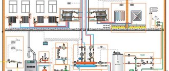
- Primary-secondary rings with hydraulic arrow and manifold
To understand how does the combined heating system work, you need to deal with such a concept as "primary - secondary rings". This is what the article is about.
Problems of the movement of the coolant in the heating system
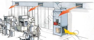
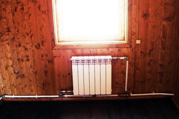
Once in apartment buildings, heating systems were two-pipe, then they began to be made one-pipe, but at the same time a problem arose: the coolant, like everything else in the world, seeks to go along a simpler path - along a bypass pipe (shown in the figure with red arrows), and not through a radiator that creates more resistance:
To force the coolant to go through the radiator, they came up with the installation of narrowing tees:
At the same time, the main pipe was installed with a larger diameter than the bypass pipe. That is, the coolant approached the narrowing tee, ran into a lot of resistance and, willy-nilly, turned to the radiator, and only a smaller part of the coolant went along the bypass section.
According to this principle, a one-pipe system is made - "Leningrad".
Such a bypass section is made for another reason. If the radiator fails, then while it is removed and replaced with a serviceable one, the coolant will go to the rest of the radiators along the bypass section.
But this is like history, we are returning "to our days."
Advantages and disadvantages
The main advantages of the scheme, because of which "Leningrad" is so popular, are:
- small costs for materials;
- ease of installation.
Another thing is when metal-plastic or polyethylene pipes are used for installation. Remember that the Leningrad distribution scheme provides for a large diameter of the supply line, while in a two-pipe system the pipe size will be smaller. Accordingly, fittings of a larger diameter are used, which means that they will cost more and, in general, the cost of work and materials will be higher.
As for the ease of installation, the statement is absolutely correct. A person who is at least a little versed in the issue will calmly put together the scheme of "Leningrad". The difficulty lies elsewhere: before installation, a careful calculation of the pipelines and the power of the radiators is required, taking into account the significant cooling of the coolant. If this is not done and the system is assembled at random, the result will be sad - only the first 3 batteries will heat, the rest will remain cold.
In fact, the merits for which the "Leningrad woman" is so valued are very illusory. It is easy to install, but difficult to design. It can boast of cheapness only if it is assembled from certain materials, and not everyone is satisfied with them.
An important drawback of the Leningrad circuit stems from its principle of operation and lies in the fact that it is very problematic to regulate the heat transfer of batteries using thermostatic valves. The figure below shows the Leningrad heating system in a two-story house, where such valves are installed on the batteries:
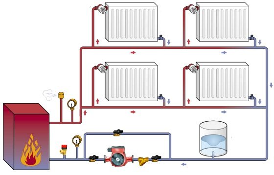
This circuit will function randomly all the time.As soon as the first radiator heats up the room to the set temperature, and the valve turns off the coolant supply, its bulk rushes to the second battery, the thermostat of which will also start to work. And so on until the very last device. When cooling, the process will be repeated, only the other way around. When everything is calculated correctly, the system will heat up more or less evenly, if not, the last batteries will never heat up.
In the Leningrad scheme, the operation of all batteries is interconnected, therefore it is pointless to install thermal heads, it is easier to balance the system manually.
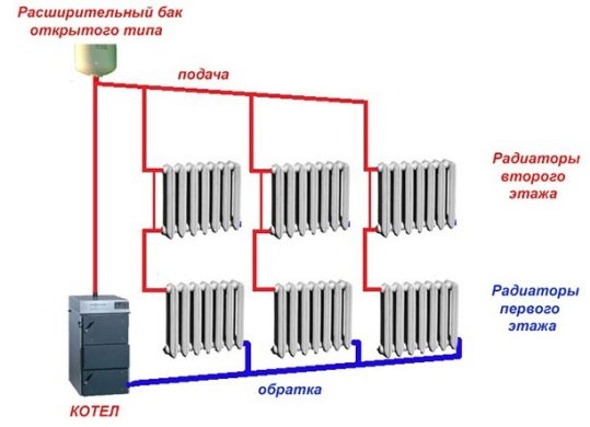
And the last thing. "Leningradka" operates rather reliably with forced circulation of the coolant, and it was conceived as part of a centralized heat supply network. When you need a non-volatile heating system without a pump, then "Leningrad" is not the best option. To get good heat transfer with natural circulation, you need a two-pipe system or a vertical one-pipe system, shown in the figure:
How to make the coolant go into the secondary ring?
But not everything is so simple, but you need to deal with the node, circled by a red rectangle (see the previous diagram) - the place of attachment of the secondary ring. Because the pipe in the primary ring is most likely of a larger diameter than the pipe in the secondary ring, so the coolant will tend to the section with less resistance. How to proceed? Consider the circuit:
The heating medium from the boiler flows in the direction of the red arrow "supply from the boiler". At point B, there is a branch from the supply to the underfloor heating. Point A is the entry point for the underfloor heating return into the primary ring.
Important! The distance between points A and B should be 150 ... 300 mm - no more!
How to "drive" the coolant in the direction of the red arrow "to the secondary"? The first option is a bypass: reducing tees are placed in places A and B and between them a pipe of smaller diameter than the supply.
The difficulty here is in calculating the diameters: you need to calculate the hydraulic resistance of the secondary and primary rings, bypass ... if we miscalculate, then there may be no movement along the secondary ring.
The second solution to the problem is to put a three-way valve at point B:
This valve will either completely close the primary ring, and the coolant will go directly to the secondary. Or it will block the way to the secondary ring. Or it will work as a bypass, letting in part of the coolant through the primary and part through the secondary ring. It seems to be good, but it is imperative to control the temperature of the coolant. This three-way valve is often equipped with an electric actuator ...
The third option is to supply a circulation pump:
The circulation pump (1) drives the coolant along the primary ring from the boiler to ... the boiler, and the pump (2) drives the coolant along the secondary ring, that is, on the warm floor.
The principle of operation of primary-secondary rings
The primary ring is a structure in the heating system that basically connects any secondary rings and also captures the adjacent boiler ring. The basic rule for secondary rings, so that they do not depend on the primary, is to observe the length between the tees of the secondary ring, which should not exceed four diameters of the primary
For example, to calculate the longest length between tees, so that the ring works freely, it is worthwhile to accurately designate the diameter of the primary ring structure. This pipe is additionally tied with copper material, since the element is conductive to high temperatures. For example: take a pipe length of 26 mm, the width of such a pipe does not exceed a few millimeters. We take 1 mm from each side of the wall, which means that the inner diameter of the tube will be 24 mm.
To calculate the distance between the tees, the resulting value (we have 24) is multiplied by 4, since the distance should be equal to four diameters.As a result, after calculations, the gap between the tees should not be more than 96 mm. In fact, all tees will necessarily be soldered together.
Each design with a hydraulic leveler has a spring-loaded check valve in every secondary ring. If you do not adhere to such recommendations, then parasitic circulation occurs through non-working places.
In addition, it is not advisable to use a circulation pump on the opposite pipeline. This often causes pressure changes due to the large distance from the expansion vessel of a closed system.
Another seemingly obvious fact, but which many people forget. No ball valves should be installed between the tees. Neglecting this rule will lead to the fact that both pumps will become dependent on the work of a neighbor.
Consider a useful tip for working with circulation pumps. So that the valve springs do not make sounds during operation, it is worth remembering one rule - the check valve is installed at a distance of 12 pipeline diameters. For example: with a pipe diameter of 23 mm, the distance between the valves will be 276 mm (23x12). Only at this distance, the valves will not make sounds.
In addition, according to this principle, it is advised to equip the pump with a length of 12 diameters of a suitable pipeline. Measure everything from the T-shaped ramifications. In these places, the turbulent type with the effect of recirculation (vortex of fluid flows). It is their formation at the corner points of the contour that creates an unpleasant noise. Moreover, this feature creates another minimum resistance.
Basic principles of hydraulic calculation of a heating system
Silent operation of the projected heating system must be ensured in any modes of its operation. Mechanical noise occurs due to the temperature lengthening of pipelines in the absence of expansion joints and fixed supports on the mains and risers of the heating system.
When using steel or copper pipes, noise propagates throughout the heating system, regardless of the distance to the noise source, due to the high sound conductivity of metals.
Hydraulic noise occurs due to significant turbulence of the flow, which occurs at an increased speed of water movement in pipelines and with a significant throttling of the coolant flow by a control valve. Therefore, at all stages of the design and hydraulic calculation of the heating system, when selecting each control valve and balance valve, when selecting heat exchangers and pumps, when analyzing temperature elongations of pipelines, it is necessary to take into account the possible source and level of noise generated in order to select the appropriate equipment and fittings for the given initial conditions.
The purpose of the hydraulic calculation, provided that the available pressure drop at the inlet of the heating system is used, is:
• determination of diameters of sections of the heating system;
• selection of control valves installed on branches, risers and heating device connections;
• selection of bypass, dividing and mixing valves;
• selection of balance valves and determination of the value of their hydraulic adjustment.
During commissioning of the heating system, the balance valves are set to the project settings.
Before proceeding with the hydraulic calculation, it is necessary to indicate the calculated heat load of each heater on the heating system diagram, equal to the calculated heat load of the room Q4. If there are two or more heaters in the room, it is necessary to divide the value of the calculated load Q4 between them.
Then the main calculated circulation ring should be selected.Each circulation ring of the heating system is a closed loop of successive sections, starting from the discharge pipe of the circulation pump and ending with the suction pipe of the circulation pump.
In a one-pipe heating system, the number of circulation rings is equal to the number of risers or horizontal branches, and in a two-pipe heating system, the number of heating devices. Balance valves must be provided for each circulating ring. Therefore, in a one-pipe heating system, the number of balance valves is equal to the number of risers or horizontal branches, and in a two-pipe heating system - the number of heating devices, where balance valves are installed on the return connection of the heater.
The main design circulation ring is taken as follows:
• in systems with a passing movement of the coolant in the mains: for one-pipe systems - a ring through the most loaded riser, for two-pipe systems - a ring through the bottom heater of the most loaded riser. Then, the circulation rings are calculated through the extreme risers (near and far);
• in systems with a dead-end movement of the coolant in the mains: for one-pipe systems - a ring through the most loaded of the most distant risers, for two-pipe systems - a ring through the bottom heater of the most loaded of the most distant risers. Then the calculation of the remaining circulation rings is carried out;
• in horizontal heating systems - a ring through the most loaded branch of the lower floor of the building.
One of two directions of hydraulic calculation of the main circulation ring should be chosen.
The first direction of hydraulic calculation consists in the fact that the diameters of the pipes and the pressure loss in the ring are determined by the specified optimal speed of movement of the coolant in each section of the main circulation ring, followed by the selection of the circulation pump.
The speed of the coolant in horizontally laid pipes should be taken at least 0.25 m / s to ensure the removal of air from them. It is recommended to take the optimal design movement of the coolant for steel pipes - up to 0.3 ... 0.5 m / s, for copper and polymer pipes - up to 0.5 ... 0.7 m / s, while limiting the value of the specific friction pressure loss R no more than 100 ... 200 Pa / m.
Based on the results of calculating the main ring, the remaining circulation rings are calculated by determining the available pressure in them and selecting the diameters according to the approximate value of the specific pressure loss Rav (by the method of specific pressure loss).
First direction of calculation it is used, as a rule, for systems with a local heat generator, for heating systems with their independent connection to heating networks, for heating systems with dependent connection to heating networks, but insufficient available pressure at the input of heating networks (except for mixing nodes with an elevator).
The required head of the circulation pump Рн, Pa, required for the selection of the standard size of the circulation pump, should be determined depending on the type of heating system:
• for vertical one-pipe and bifilar systems according to the formula:
Rn = ΔPs.о. - Re
• for horizontal one-pipe and bifilar, two-pipe systems according to the formula:
Rn = ΔPs.о. - 0.4 Re
where: ΔP.o - pressure loss. in the main design circulation ring, Pa;
Pe is the natural circulation pressure arising from the cooling of water in heating devices and pipes of the circulation ring, Pa.
The second direction of hydraulic calculation consists in the fact that the selection of pipe diameters in the design sections and the determination of pressure losses in the circulation ring is carried out according to the initially specified value of the available circulation pressure for the heating system. In this case, the diameters of the sections are selected according to the approximate value of the specific pressure loss Rav (by the method of specific pressure loss). According to this principle, the calculation of heating systems with natural circulation, heating systems with dependent connection to heating networks (with mixing in the elevator; with a mixing pump on the lintel with sufficient available pressure at the input of heating networks; without mixing with sufficient available pressure at the input of heating networks) ...
As the initial parameter of the hydraulic calculation, it is necessary to determine the value of the available circulating pressure drop ΔPР, which in natural circulation systems is equal to
ΔPР = Pe,
and in pumping systems it is determined depending on the type of heating system:
• for vertical one-pipe and bifilar systems according to the formula:
ΔPР = Rn + Re
• for horizontal one-pipe and bifilar, two-pipe systems according to the formula:
ΔPР = Rn + 0.4. Re