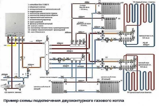
Gas heating systems are by far the most popular type of heating equipment used in private houses. They can be used not only as the only source of thermal energy, but also in a unified combination with heaters operating on different types of fuel. In this case, not only correct installation plays a very important role, but also the connection diagram of a double-circuit gas boiler to all communications and its interaction with all other equipment.
- 2 Differences between gas boilers of the heating system
- 3 Where can I connect the boiler to the heating system
- 4 Diagram of connecting the boiler to the heating system
- 5 Connecting the boiler to the gas pipeline and water supply
- 6 Conclusion
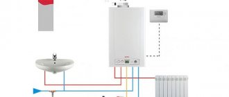
Connecting a gas boiler to the heating system
Any owner of a city apartment or private house dreams of autonomous gas heating. Today, only such a device is capable of providing a comfortable temperature in an apartment at minimal cost. Connecting a double-circuit gas boiler is a very important matter, for which you should issue a permit... It must be installed only if finances allow you to purchase a gas double-circuit boiler with a boiler and a full set of automation. According to TU, such housing must have conditions for the installation of this structure.
If there is not a lot of finance, and the appearance of hot water in the apartment is not expected, then it is best to buy a simple single-level gas boiler. Such an installation costs much more than a water heater, however, given how much it will cost to install a gas meter, with existing tariffs such a structure will easily pay off in 1.5 years, or even earlier.
To connect the boiler to the heating system, you will need the following items:
- scheme;
- water purification filter;
- water heater;
- boiler - single-circuit or double-circuit;
- cold and hot water taps.


Joint work of gas and electric boilers
Combining a gas boiler with an electric boiler in one circuit, as a result of which a heating system with two boilers is created, can be implemented quite simply. Both serial and parallel connection is possible. In this case, a parallel connection is preferable, because it is possible to leave one boiler running while the other is completely stopped, switched off or replaced. Such a system can be completely closed, and ethylene glycol for heating systems or ordinary water can be used as a heat carrier.
Differences between gas boilers of the heating system
Such heating structures are easily installed independently using schemes. Connecting other gas boilers will require special skills. It should be noted that many specialized firms are ready to take on work related to the preparation of premises and execution of all required documents.
A typical boiler is quite simple: a gas burner and a heat exchanger. Gas, water are connected to it and the exhaust is discharged into the chimney. They start using it only after completing all the documents.
A double-circuit heating boiler with a water heater and automation is multifunctional and simple. It is just as easy to install as usual. Automation is used in this way: a system with a microprocessor and a double thermostat monitors the temperature outside and in the apartment, and, according to the established program, reduces heating to a minimum if people are not at home. Gas is consumed by such an installation 50% less than with manual or automatic regulation.Savings are very significant in harsh weather.
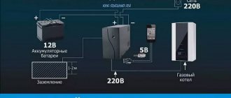
Such a home boiler room has one serious drawback - if the power supply is interrupted, then the automation turns off, and the double-circuit unit switches to the mode of minimum heating of the room. Therefore, for a double-circuit heating boiler, additional costs are required for a guaranteed power supply.
Where can the boiler be connected to the heating system
There are the following requirements to connect a gas boiler:
- It must be installed in a boiler room, which is a separate room with a minimum area of 4 m2 and a ceiling height of at least 2.55 m.
- The boiler room must be equipped with one window. The minimum door width should be 0.8 m.
- The boiler room must be finished with non-combustible materials, while a raised floor and a brick oven are strictly prohibited.
- Air must enter this room through a non-closable through air duct.
For wall-mounted hot water and other boilers the following rules apply:
- The boiler exhaust must necessarily go into a separate chimney without using ventilation ducts. This is explained by the fact that hazardous combustion products can get into the adjacent room.
- The horizontal part of the flue must be at least 3 m long and have at least three turning nodes.
- The flue must have a vertical outlet, while it must be raised above the highest point of the gable on a flat roof by at least 1 m.
- Due to the fact that after cooling of the combustion products, hazardous substances are formed, the chimney must therefore be made of chemically heat-resistant materials.
When installing a wall-mounted hot water boiler in the kitchen you must adhere to the following rules:
- There must be free space under the unit.
- The height of the suspension structure in accordance with the cut of the highest branch pipe cannot be lower than the top of the washing spout.
- The floor under the unit must be covered with a non-combustible durable metal sheet.
- The combustion room should not contain any cavities in which an explosive gas mixture can accumulate.
Gas boiler it is not recommended to install in the following cases:
- If you plan to install it in an apartment building or an old Khrushchev, in which there is no main gas duct.
- If there is a false ceiling in the kitchen, which is not planned to be dismantled. A capital mezzanine will also not work.
In all other cases, you can install and connect gas boilers in your own apartment. Any structure is installed in a private house. If the extension for the boiler room is made outside, the relevant authorities will find fault less.
For a small private house, it is best to install a wall-mounted boiler, because you will not need to install a concrete or brick pallet under it. Automation of gas boilers does not consume too much electricity.
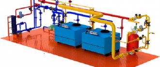
Heating systems with two or more boilers
By including two or more boilers in the heating scheme, one can pursue the goal of not only increasing heating power, but also reducing energy consumption. As already mentioned, the heating system is initially designed to work in the coldest five-day period of the year, the rest of the time the boiler works half-heartedly. Suppose that the energy consumption of your heating system is 55 kW and you are choosing a boiler of this power. The entire boiler capacity will be used only a few days a year; the rest of the time, less power is needed for heating. Modern boilers are usually equipped with two-stage blast burners, which means that both stages of the burner will work only a few days a year, the rest of the time only one stage will work, but its capacity may be too much for the off-season.Therefore, instead of one 55 kW boiler, you can install two boilers, for example, 25 and 30 kW, or three boilers: two 20 kW and one 15 kW. Then, on any day of the year, less powerful boilers can work in the system, and at peak load everything is turned on. If each of the boilers has a two-stage burner, then the setting of the boilers can be much more flexible: boilers can simultaneously operate in the system in different modes of burner operation. And this directly affects the efficiency of the system.
In addition, installing several boilers instead of one solves several more problems. Large-capacity boilers are heavy units that first need to be brought and brought into the room. The use of several small boilers greatly simplifies this task: a small boiler easily goes through doorways and is much lighter than a large one. If suddenly, during the operation of the system, one of the boilers fails (the boilers are extremely reliable, but suddenly this happens), then it can be turned off from the system and calmly engaged in repairs, while the heating system will remain in working mode. The remaining working boiler may not fully warm, but it will not freeze either, in any case, the system will not need to be “drained”.
The inclusion of several boilers in the heating system can be carried out in a parallel scheme and according to the scheme of primary-secondary rings.
When operating in a parallel circuit (Fig. 63) with the automation of one of the boilers turned off, the return water is passed through the idle boiler, which means that it overcomes the hydraulic resistance in the boiler circuit and consumes electricity by the circulation pump. In addition, the return (cooled heat carrier), which has passed through the idle boiler, is mixed with the supply (heated heat carrier) from the operating boiler. This boiler has to increase the heating of the water in order to compensate for the mixing of the return from the idle boiler. In order to prevent the mixing of cold water from a non-operating boiler with hot water from an operating boiler, you need to manually close the pipelines with valves or supply them with automation and servo drives.
Fig. 63. Heating scheme of two half rings with increasing power by installing a second boiler
Connecting boilers according to the scheme of primary-secondary rings (Fig. 64) does not provide for such types of automation. When one of the boilers is turned off, the coolant passing through the primary ring simply does not notice the “loss of a soldier”. The hydraulic resistance at the section where the AB boiler is connected is extremely small, so there is no need for the coolant to flow into the boiler circuit and it calmly follows along the primary ring as if the valves in the disconnected boiler were closed, which in fact are not there. In general, in this scheme, everything happens in the same way as in the scheme for connecting the secondary heating rings with the only difference that in this case, not heat consumers, but generators, “sit” on the secondary rings. Practice shows that the inclusion of more than four boilers in the heating system is not economically feasible.
Fig. 64. Schematic diagram of connecting boilers to the heating system on primary-secondary rings
several typical schemes have been developed using hydrocollectors "GidroLOGO" for heating systems with two or more boilers (Fig. 65–67).
Fig. 65. Heating scheme with two primary rings with a common area. Suitable for boiler houses of any capacity with reserve boilers, or for boiler houses of large (over 80 kW) capacity and a small number of consumers.
Fig. 66. Two-boiler heating circuit with two primary half-rings. Convenient for a large number of consumers with high requirements to the supply temperature. The total power of consumers of the "left" and "right" wing should not differ greatly. Boiler pump capacities should be approximately the same.
Fig. 67.A universal combined heating scheme with any number of boilers and any number of consumers (in the distribution group, conventional collectors or hydrocollectors "HydroLOGO" are used, in the secondary rings, horizontal or vertical hydrocollectors ("HydroLOGO") are used
Figure 67 shows a universal scheme for any number of boilers (but no more than four) and an almost unlimited number of consumers. In it, each of the boilers is connected to a distribution group consisting of two conventional collectors or “HydroLOGO” collectors installed in parallel and closed to the hot water supply boiler. On the collectors, each ring from boiler to boiler has a common section. Small hydrocollectors of the “element-Micro” type with miniature mixing units and circulation pumps are connected to the distribution group. The entire heating scheme from boilers to element-Micro hydrocollectors is an ordinary classical heating scheme, which forms several (according to the number of hydrocollectors) primary rings. Secondary rings with heat consumers are connected to the primary rings. Each of the rings, located at a higher stage, uses the lower ring as its own boiler and expansion tank, that is, it takes heat from it and discharges waste water. This installation scheme is becoming a common way of arranging "advanced" boiler rooms both in small houses and in large objects with a large number of heating circuits, which allows fine-tuning of each circuit to be made.
To make it clearer what the versatility of this scheme is, let's take a closer look at it. What is a conventional collector? By and large, this is a group of tees assembled in one line. For example, in a heating circuit there is one boiler, and the circuit itself is aimed at priority preparation of hot water. This means that hot water, leaving the boiler, goes straight to the boiler, giving up some of the heat to prepare hot water, it returns to the boiler. Let's add another boiler to the circuit, which means that one tee must be installed on the supply and return lines and a second boiler connected to them. But what if there are four of these boilers? And everything is simple, you need to install three additional tees for the supply and return of the first boiler and connect three additional boilers to these tees or not install tees in the circuit, but replace them with collectors with four outlets. So it turned out that we connect all four boilers by supply to one collector, and by return to another. The collectors themselves are connected to a hot water boiler. It turned out a heating ring with a common area on the collectors and boiler connection pipes. Now we can safely turn off or turn on some of the boilers, and the system will continue to function, only the coolant flow rate will change in it.
However, in our heating system, it is necessary to envisage not only the heating of domestic water, but also radiator heating systems and "warm floors". Therefore, for each new heating circuit for supply and return, you need to install a tee and these tees need as many as we have conceived of heating circuits. Why do we need so many tees, isn't it better to replace them with collectors? But we already have two collectors in the system, so we will simply increase them or immediately install collectors with such a number of outlets so that they are enough for connecting boilers and heating circuits. We find collectors with the required number of taps or assemble them from ready-made parts or use ready-made hydrocollectors. For further expansion of the system, if required, we can install collectors with a large number of branches and temporarily plug them with ball valves or plugs.The result is a classic collector heating system, in which the supply ends with its own collector, the return line with its own, and pipes went from each collector to separate heating systems. We close the collectors themselves with a boiler, which, depending on the speed at which the circulation pump is turned on, may have a hard or soft priority or not, since it turns out to be connected to the circuit in parallel with other heating circuits.
Now it's time to think about the heating system with primary-secondary rings. We close each pair of pipes coming out of the supply and return collectors with an element-Mini hydrocollector (or other hydrocollectors) and we will obtain heating primary rings. Through the pumping and mixing units, we will connect heating rings to these hydrocollectors according to the primary-secondary scheme, those that we consider necessary (radiator, warm floors, convector) and in the amount we need. Please note that in the event of refusals in heat requests even for all secondary heating circuits, the system continues to work because it contains not one primary ring, but several - according to the number of hydrocollectors. In each primary ring, the coolant from the boiler (s) passes through the supply manifold, from there it enters the hydrocollector and returns to the return manifold and to the boiler.
As it turns out, it is not so difficult to make a heating system with at least one boiler, at least with several and with any number of consumers, the main thing is to select the required power of the boiler (boilers) and choose the correct cross-section of the hydrocollectors, but we have already talked about this in sufficient detail.
Source: “Heating at home. Calculation and installation of systems "2011. Savelyev A.A.
Diagram of connecting the boiler to the heating system
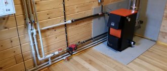
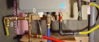
The heating boiler connection diagram does not allow its body to touch tightly to any of the walls. They begin to make piping of the boiler, that is, three systems are connected: electrical, gas and hydraulic. Gas piping should only be carried out by a gas specialist and should be performed last, after all systems have been connected.
The hydraulic and electrical connections can be made by yourself. In this case, follow the instructions supplied with the boiler. A typical strapping scheme helps in this. For any boiler, the following conditions must be met:
- in the heat exchanger, water and hot gases must necessarily go in a counterflow, because with any automation it can explode;
- it is very important not to confuse the cold and hot water pipes.
After completing the hydraulic piping the entire system should be carefully examined again.
If antifreeze has been used for the heating system, then it must be drained and the system flushed with water several times. Antifreeze admixture in the water can cause an explosion.
It is advisable to use coarse filters. They must be located at the bottom of the system. A dangerous situation can arise when dirt accumulates between the thin fins of the heat exchanger. At the beginning and end of the heating season, the sludge must be drained through the "mud trucks", their condition must be checked and the entire system must be flushed.
If the structure has a built-in expansion tank and a de-airing system, then it is better to remove the old tank. At the same time, they tightly shut off the old tap, before checking its condition. A dangerous situation can arise due to air leaks.
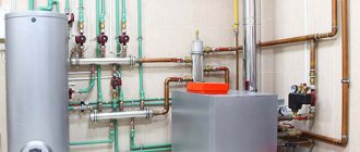
Dual fuel heating boilers
To increase the reliability of heating and to avoid interruptions in the operation of the heating system, dual-fuel heating boilers operating on different types of fuel are used. Combined boilers are manufactured only in floor-standing design due to the rather large weight of the unit.A universal unit can have one or two combustion chambers and one heat exchanger (boiler).
The most popular scheme is the use of gas and wood to heat the coolant. It should be borne in mind that solid fuel boilers can only work in open heating systems. To realize the advantages of a closed system, an additional circuit for the heating system is sometimes installed in the tank of a universal boiler.
There are several types of dual-fuel combined boilers:
- gas + liquid fuel;
- gas + solid fuel;
- solid fuel + electricity.
Connecting the boiler to the gas pipeline and water supply
Such a scheme for connecting a gas boiler does not differ at all from the scheme for connecting equipment to the heating system, there is only the difference in the diameter of pipes and valves... Shut-off valves must have detachable connections. Hot water is connected on the right side, cold water on the left.
Much attention must be paid to the scheme for connecting the boiler to the gas pipeline. This is due to the fact that if the device is connected to the gas incorrectly, an explosion may occur.
In the center of the boiler there is a pipe and work begins with its connection to a branch of the gas pipeline with a valve installed. Protect the heater against small debris. A special valve is installed on the valve used to stop the gas supply. Then, using paint and tow, they begin to seal all threaded connections. The use of other means is strictly prohibited.
It is not recommended to turn on the device immediately after installation. All connections must be carefully checked to ensure that all steps are followed correctly.
Boiler installation
The process is pretty straightforward. If the scheme for connecting heating to a gas boiler involves the installation of a floor heating device, the device is securely fixed to the floor according to the instructions. If the boiler drum is made in a wall-mounted format, then it is necessary to mark the places on the wall for drilling the brackets on which the heater will be fixed.
In order for the installation to go smoothly, it is necessary to carefully align all the details, fix the brackets correctly and make sure that the dimensions of the boiler and the selected surface are proportional.
Do not forget about safety requirements:
- the gas boiler must be installed in a room with a ventilation window;
- there should be no other devices near it;
- during installation, the correct installation location must be chosen;
- a chimney and ventilation are required.
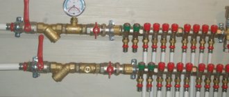
Connecting the boiler to the circuit
The next stage of work, which provides for a connection diagram for a heating boiler for two floors or for an apartment, is the piping of the device with a heating circuit pipeline. Modern boilers are equipped with special pipes to which supply and return are supplied. The nozzles are located close to the end of the boiler and the pipes must be connected to them in accordance with the recommendations from the instructions for the device.
At this stage of work, you should definitely use insulating materials - sealants, which will reliably protect the connection points of pipelines to the boiler from leaks. Another recommended condition is the installation of a special filter on the check valve. It is designed to protect the internal elements of the boiler from destructive impurities that are in the composition of the coolant.
Also, connecting the boiler to the heating system implies the installation of shut-off valves, namely, shut-off valves, which are installed on the return and coolant supply pipeline. Such taps prevent air from entering the system and pouring out the coolant from the circuit. In the event of a boiler breakdown, they will help to carry out repair work as simply as possible.If you need to choose a gas boiler for an apartment, then our article "Choosing a gas boiler for an apartment: an overview of equipment and installation rules" will be useful.
Connecting the boiler to the water supply
The principle of work at this stage is similar to the work discussed in the previous section. The only difference is the choice of a different branch pipe intended for connection to the central water supply circuit. Having selected pipes that are suitable in diameter, as well as having prepared filters and stopcocks, you can start working.
For example, connecting the Cooper OK 15 boiler to the main pipeline, the heating connection diagram of which involves the use of detachable connections, for ease of installation, the master can start by looking for nozzles. Having brought the water supply pipelines to the boiler nozzles, they must be connected and insulated. If the water in the water supply system is hard and contains heavy impurities, it is recommended to use filters that must be changed periodically.