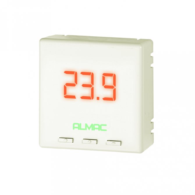
A thermostat is a circuit breaker that performs only one main function - supply (disconnect) voltage to the load. A heating section, mats, IR foil or other electrical devices can be used as a load.
The supply (disconnection) of voltage to the warm floor occurs depending on the readings of the temperature sensor or by time (for programmable thermostats).
Before checking the thermostat, it is necessary to check the correctness of the program settings (for programmable thermostats) and the correct choice of the temperature sensor (setting of jumpers for thermostats with two temperature sensors).
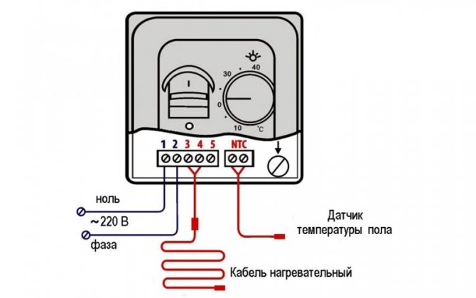
Thermostat connection diagram
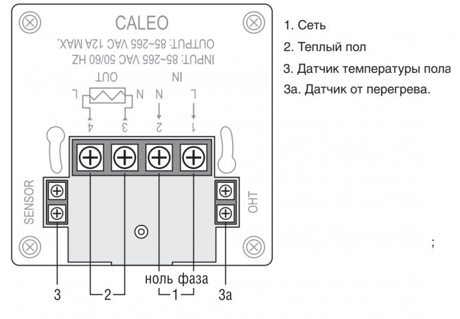
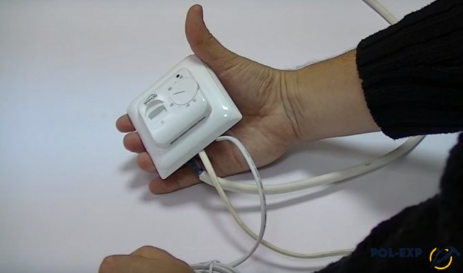
Let's consider the connection of the simplest and most common thermostat for underfloor heating RTC 70.26.
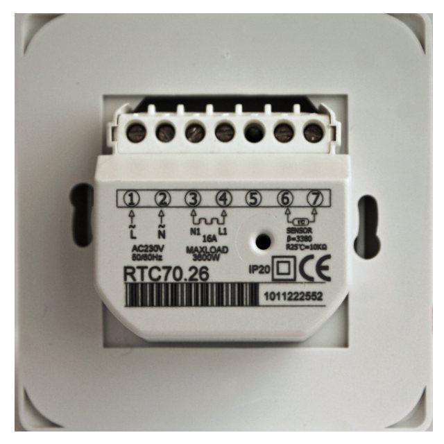
As you can see in the photo, the thermostat has a connector for connecting wires.
- Contact No. 1 (L) - phase connection from the socket or control panel.
- Contact No. 2 (N) - connection of the neutral wire from the socket or control panel.
- Contact No. 3 (N) - connection of the neutral wire going to the heating element - underfloor heating.
- Contact No. 4 (L) - connection of the phase going to the heating element - underfloor heating.
- Contact number 5 is free.
- Contacts No. 6 and No. 7 - connection of two wires from the temperature sensor (sensor).
Please note that the sensor resistance is indicated on the thermostat. The use of a sensor with a different resistance leads to incorrect operation of the thermostat. The most common temperature sensors are 6, 10 and 15 kΩ. For example, the RTC series thermostats are equipped with 10 kΩ temperature sensors.
Attention!
All actions for connecting, replacing the thermostat or replacing the temperature sensor are performed with the voltage disconnected!
Types of temperature sensors
Depending on the type, the instruction for the underfloor heating sensor may change. In total, the sensors are divided into two large categories - for reading the temperature indicators of the floor covering and for indoor air.

How to choose a phase meter - an overview, purpose, principle of operation, scope + instructions for use with a photo

How to make a transformer with your own hands - step by step instructions, diagram, drawings, list of materials + photo of a finished homemade transformer


Which hidden wiring detector is better? TOP 10 best manufacturers with photos and descriptions
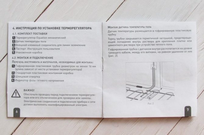

Depending on this, both the design of the sensor and its installation can be changed. Let's start with the first option, which provides for installation under the floor covering.


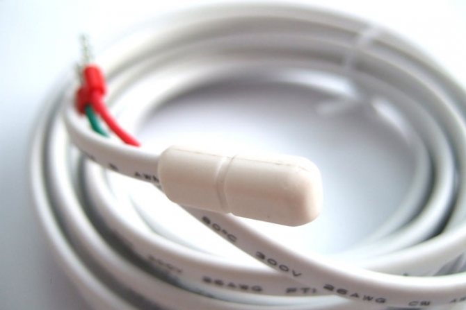
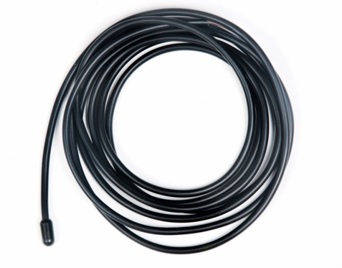
In all cases, the sensor has the same design - a wire, at the end of which there is a thermoelement for collecting temperature data, which is placed in a plastic or glass flask, less often a ceramic one.


If the floor is not collapsible, then the element itself will need to be placed in additional protection so that nothing will harm it. As you can see, the choice of flooring affects how the temperature sensor should be installed.
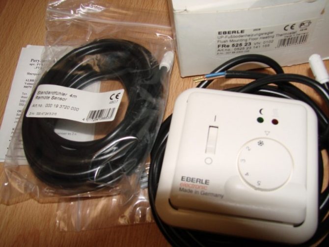

Checking the performance of the thermostat for a warm floor
The sequence of checking the thermostat and temperature sensor.
- We check the correctness of the connection of the wires.We are guided by the connection diagram according to the passport. For thermostats of the RTC, TC and E series, you can follow the diagram above.
- We set the temperature regulator to minimum.
- We apply voltage to the thermostat and check the voltage coming to the thermostat (pins 1 and 2). The voltage should be 220 V.
- We translate the toggle switch to the ON position.
- Turn the temperature regulator clockwise to maximum. In a working thermostat, when the temperature rises, the relay should work (a click is heard). In this case, the voltage of 220 V is supplied to contacts No. 3 and No. 4.
When the temperature decreases (turning the regulator counterclockwise), the relay must turn off the voltage supply to the heated floor. This confirms the fact that the thermostat is working.
If, when the temperature rises to a maximum, there is no voltage on contacts No. 3 and No. 4, then we check the temperature sensor.
It is simple to identify a temperature sensor malfunction, it is enough to measure its resistance and compare it with those stated in the passport. When the temperature sensor heats up, its resistance decreases.
Underfloor heating sensor malfunction
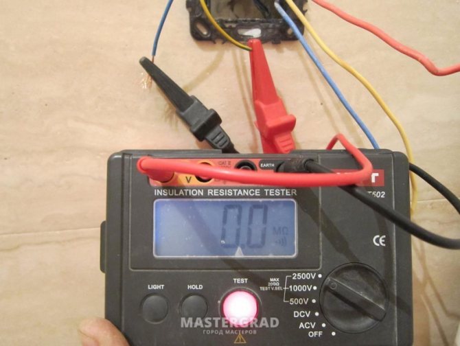
If everything is in order with the thermostat and heating elements, and the electric floor heats up weakly or, at all, does not work, then this may indicate a breakdown of the temperature sensor. You can check it with a multimeter. Resistance is measured - if its indicators are within the normal range (do not deviate by more than 5% from the passport), then the sensor is in good order. If the deviations are significant, a replacement is required.
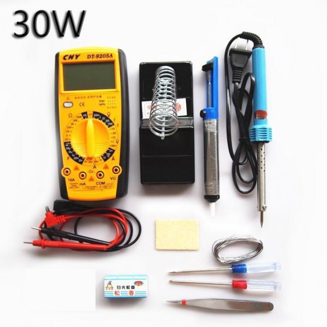

Multimeter kit for testing resistance in the underfloor heating system
To measure the resistance and replace the sensor, it is necessary to disconnect it from the thermostat and remove it from the corrugated pipe.
Temperature and resistance of 10 kΩ floor sensor
| Temperature, ° С | Resistance, Ohm |
| 5 | 22070 |
| 10 | 17960 |
| 20 | 12091 |
| 30 | 8312 |
| 40 | 5827 |
If the resistance differs from that stated in the passport, then it is necessary to replace it. The cost of a temperature sensor on the market is from 200 to 300 rubles apiece.
Note. In programmable thermostats, in the event of a temperature sensor malfunction, a corresponding message is displayed on the panel.
What should be the resistance of an electric floor heating
Underfloor heating is most often produced in the form of a heating cable or mats:
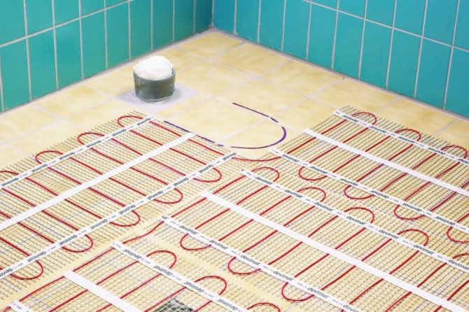
Heating mats represent a heating cable laid in a certain way and fixed in this position. In addition to the fact that this option has a much simpler installation, it has a fixed power per square meter, which does not change.
But the power per square meter of a floor made with an ordinary cable can vary greatly, depending on how it is placed on the surface, with what density, how many turns are made and what is the distance between them.
If you know what the power of the kit is, by measuring its resistance, it will not be difficult for you to check its serviceability and efficiency:
It is enough to use Ohm's law, namely the following formula:
P = U2 / Rwhere P, Watt - power; U, Volt - mains voltage, usually 220 Volts are taken into account; R, Ohm - Resistance;
Example: Thus, knowing that a heating mat with a total power of 800 W is flooded in the screed, and the multimeter showed a resistance of about 60 ohms, you can check how the actual indicators correspond to the declared ones:
P = 220 2/60 = 806.7 W - which is very close to the nominal value, which means the floor is in good order.
If you do not know the power of the installed electric heating system, you only roughly understand the surface area that it heats and where it is installed, diagnostics should be carried out as follows:
Methods for checking the performance of a thermostat for a warm floor
You can check the health of the thermostat by replacing it with another known good thermostat.If there is no second thermostat, then you can connect the warm floors "directly" to the 220 V network bypassing the thermostat and make sure that the "warm floor" is working.
For this:
- turn off the voltage;
- to the wire connected to contact 1 (L- phase) we connect wire 4 (L- phase to the load);
- connect wire 3 (N-zero load) to the wire connected to pin 2 (N-zero);
- we apply voltage and wait for some time, for example 1 hour. If the floor becomes warm, then there is a malfunction in the thermostat.
We de-energize the system, replace the faulty thermostat with a serviceable one.
I am glad if you were able to figure it out on your own, but if you have any questions, then call the numbers listed on the site and - we will figure it out together.
How to measure the resistance of a warm floor yourself using a multimeter
Below, we bring to your attention a detailed step-by-step instruction for measuring the resistance of a warm floor with a multimeter, with an analysis of all possible results obtained.
1. Usually electric underfloor heating has the following design:
- Two cores of a heating circuit and a protective braid. At the same time, by design, there are models in which the conductors of directly heating elements are located:
- from different ends - single-core heating cable
- on the one hand - two-core. The other end is insulated. The preparatory stage begins with removing the insulation from the circuit conductors, for the convenience of making measurements. 2. On the multimeter it is necessary set resistance measurement mode... Sufficient limit 200-1000 Ohm, depending on the model of the measuring device.
Place the test leads in the connectors:
- red to "VmA"
- black in "COM" 3. Press the conductive pin at the end of each probe against the prepared conductors, each to his own. The order is not important. The main thing is that these elements do not overlap with each other.
4. Possible resultswhich you can see on the multimeter screen when measuring:
"1" - Open circuit... The conductive core is damaged, you need to look for the breakage point.
"0" - Short circuit... Any value close to 0 indicates a short, most likely due to damage to the circuit's insulation.
Any other meaning - this is his inner resistance.
Now that you know this value, it remains to interpret it correctly. To understand whether it is normal, how effectively the floor works, whether the heating cable is the cause of the malfunction or a problem in other elements - the thermostat or the mains voltage.
Replacing the temperature sensor
If the underfloor heating temperature sensor is out of order, then it will have to be replaced. Otherwise, the thermostat will not be able to control the heating system. Diagnostics with a tester will help to find out the cause of the breakdown. As a rule, it identifies two causes of a malfunction - both of them are associated with contacts (either it is there where it is not needed, or it is absent where it is needed).


Electronic tester
The first step is to test the input wires - for this you have to disassemble the regulator body. When the power supply is on, the tester checks the presence of voltage in the wires. If there is no power, then one of the switches does not work - then the operability of the devices in the network is checked up to the place where the regulator is installed. If there is voltage at the input contacts, then the test continues already at the weekend. With the current off, the wires of the thermal circuit are disconnected from the regulator. If in this case, when the energy is turned on, there is no voltage on the output wires, then the breakdown lurks in the control unit or in the sensor itself. The resistance of the sensor is checked with an ohmmeter. If the sensor does not work, it should be dismantled if possible and a new one should be installed.
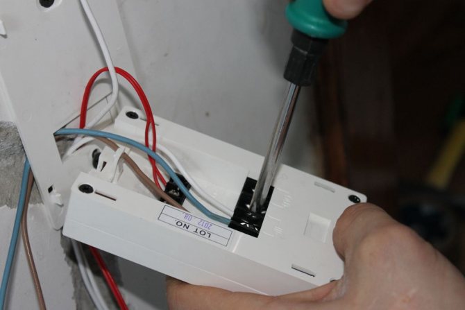

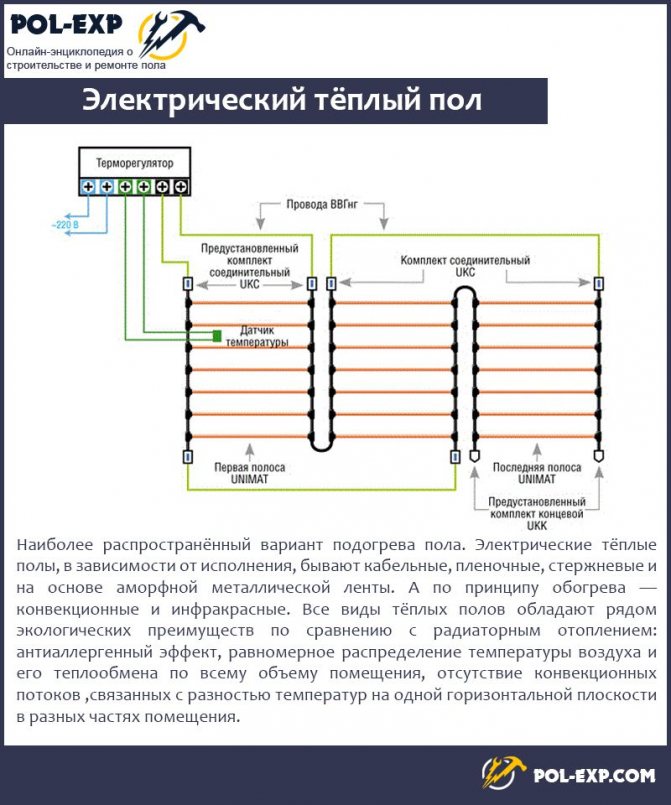
Connecting the thermostat to the warm floor
Attention! The sensor cannot be repaired, it can only be replaced with a new one.In this case, you will have to buy a new regulator.


