Features of the installation of gas boilers and furnace equipment
The installation of gas boilers must be carried out in accordance with the requirements of regulatory documents. The tenants themselves, the owners of the building cannot install gas equipment. It should be installed in accordance with a project that can only be developed by an organization licensed to do so.
Gas boilers are also installed (connected) by specialists from a licensed organization. Trading companies, as a rule, have permits for after-sales service of automated gas equipment, often for design and installation. Therefore, it is convenient to use the services of one organization.
Below, for informational purposes, the basic requirements for the places where boilers operating on natural gas can be installed (connected to the gas main) are given. But the construction of such structures must be carried out in accordance with the project and the requirements of the standards.
Different requirements for boilers with a closed and open combustion chamber
All boilers are classified according to the type of combustion chamber and the way it is ventilated. The closed combustion chamber is ventilated forcibly using a fan built into the boiler.
This allows you to do without a high chimney, but only with a horizontal section of the pipe and take air for the burner from the street through an air duct or the same chimney (coaxial chimney).
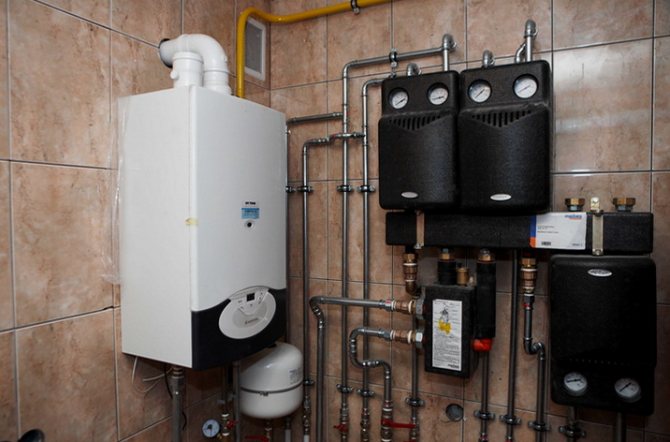
Therefore, the requirements for the installation site of one low-power (up to 30 kW) wall-mounted boiler with a closed combustion chamber are not so stringent. It can be installed in a dry utility room, including the kitchen.
Installation of gas equipment in living rooms is prohibited, in the bathroom is prohibited
Boilers with an open burner are another matter. They work for a high chimney (above the ridge of the roof), which creates a natural draft through the combustion chamber. And the air is taken directly from the room.
The presence of such a combustion chamber entails the main limitation - these boilers must be installed in separate rooms specially allocated for them - furnace (boiler rooms).
Learn more about the features of boilers with different combustion chambers. And also learn about choosing an economical boiler and creating an economical heating system.
Next, we will consider in more detail the requirements for the placement of boilers within the furnace, and for this room.
Where can the furnace (boiler room) be located
The room for installing boilers can be located on any floor of a private house, including in the basement and basement, as well as in the attic and on the roof.
Those. under the furnace, you can adapt a room within the house with dimensions not less than the standard, the doors from which lead to the street. And also equipped with a window and a ventilation grill of a certain area, etc. The furnace can be located in a separate building.
What and how can be placed in the furnace
The free passage from the front side of the installed gas equipment must be at least 1 meter wide. The furnace can accommodate up to 4 units of gas heating equipment with closed combustion chambers, but with a total capacity of no more than 200 kW.
Furnace dimensions
The height of the ceilings in the furnace (boiler room) is not less than 2.2 meters, the floor area is not less than 4 square meters. for one boiler. But the volume of the furnace is regulated depending on the capacity of the installed gas equipment: - up to 30 kW inclusive - not less than 7.5 cubic meters; - 30 - 60 kW inclusively - not less than 13.5 cubic meters; - 60 - 200 kW - at least 15 cubic meters

What is equipped with a furnace
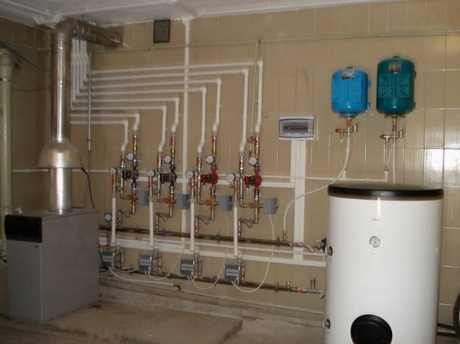
The furnace is equipped with doors to the street with a width of at least 0.8 meters, as well as a window for natural lighting with an area of at least 0.3 square meters. 10 cubic meters. furnace.
The furnace is supplied with a single-phase 220 V power supply, made in accordance with the PUE, as well as a water supply system connected to heating and hot water supply, as well as a sewage system that can receive water in case of emergency flooding, including in the volumes of a boiler and a buffer tank.
The presence in the boiler room of combustible, fire hazardous materials, including finishing on the walls, is not allowed. The gas main within the furnace must be equipped with a shut-off device, one for each boiler.
How the furnace (boiler room) should be ventilated
The furnace must be equipped with exhaust ventilation, possibly connected to the ventilation system of the entire building. Fresh air can be supplied to the boilers through the ventilation grill, which is installed at the bottom of the door or wall.
Moreover, the area of the holes in this grate should not be less than 8 square cm per one kilowatt of boiler power. And if the inflow from inside the building is at least 30 cm square. for 1 kW.
Chimney
The values of the minimum diameter of the chimney depending on the boiler output are given in the table.
But the basic rule is this - the cross-sectional area of the chimney should not be less than the area of the outlet in the boiler.
Each chimney must have an inspection hole located at least 25 cm below the chimney inlet.
For stable operation, the chimney must be above the roof ridge. Also, the chimney trunk (vertical part) must be absolutely straight.
This information is provided for informational purposes only to form a general idea of the furnace in private houses. When building a room for placing gas equipment, it is necessary to be guided by design solutions and the requirements of regulatory documents.
Determination of the dimensions of the combustion chamber, convection flue and placement of burners
The combustion chamber of the designed boiler is a parallelepiped (at - width, bt - depth, ht - height)
The volume of the combustion chamber is limited by the axial plane of the wall and ceiling wall tubes. The section of the furnace along the axes of the pipes of the screens fт is determined on the basis of the density of heat release tested in practice along the section of the furnace qf
fт =, m2 (9)
The width and depth of the combustion chamber are selected based on the dimensions of the flame of the burners and their heat output. The course project uses Weishaupt [] automatic burners. The dimensions of the section of the combustion chamber are determined according to the nomogram in Figure 9.1
Figure 9.1
Heat output of the burner
, kW (9.1)
where Вр is the volumetric consumption of natural gas, m3 / h;
- the lowest heat of combustion of gas, kJ / m3.
In boilers with low productivity (up to 25 t / h), one burner is installed per boiler. The type of suitable burner is selected from the catalog [].
The result of the choice of the burner is presented in table. 9.1
Table 9.1
| Burner type | amount |
| Monarh gas-oil 1000 ... 1000 kW |
The volume of the boiler combustion chamber is selected based on the permissible thermal stress of the combustion volume.
, m3 (9.2)
The results of calculating the section, volume and height of the combustion chamber are presented in table. 9.2
Table 9.2
| , m3 / s | , kJ / m3 | , kW / m2 | , m2 | , kW / m2 | , m3 | ht, m |
The smallest section of the convective gas duct is determined based on the volume of gases at the entrance to the mine and on their economically optimal speed
, m2 (9.3)
where Fk is the section, m2; - temperature of flue gases at the entrance to the gas duct, оС; K is the coefficient of the free flow area; - optimal speed of flue gases, m / s.
Free flow area ratio
, (9.4)
where S1 is the pipe pitch in the cross-section transverse to the gas flow, mm; d - outer diameter of pipes, mm.
S1 S1 d
gas flow
Pre-selected d = 51 mm, S1 = 100 mm. The calculation results are presented in table. 9.3
Table 9.3
| , m3 / h | , m3 / s | Vg, m3 / m3 | , oC | , m / s | S, mm | d, mm | TO | , m2 |
The calculated surface of the walls of the combustion chamber
, m2 (9.5)
Estimated volume of the combustion chamber
, m3 (9.6)
The result of the determination is presented in table. 9.4
Table 9.4
| , m | , m | , m | , m2 | , m2 |
Thermal calculation of the combustion chamber
10.1. Useful heat dissipation in the firebox
, kJ / m3 (10)
where is the net calorific value of dry natural gas, kJ / m3; - the heat of the outside air. Since cold air is not preheated
, kJ / m3 (10.1)
The calculation results are given in table. 10.1
Table 10.1
| , kJ / m3 | , % | , kJ / m3 | , kJ / m3 | , kJ / m3 |
Theoretical (adiabatic) fuel combustion temperature.
Temperature, υa is determined from the table. 7.3 by interpolating the enthalpy of the combustion chamber gases using the formula
, оС (10.2)
The calculation result is presented in table. 10.2
Table 10.2
| , kJ / m3 | , оС | , оС | , kJ / m3 | , kJ / m3 | , оС |
Pros and cons of a boiler with skeletal heat exchanger
Stoves equipped with a water circuit, which are used to heat an individual cottage, have both advantages and disadvantages. The homeowner must take them into account before deciding to install such a heating source.
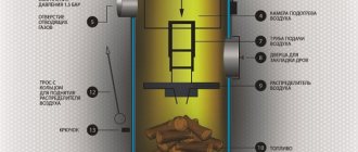
In addition, you will need to choose the size of the firebox, which, in terms of thermal indicators, will provide reliable heating of the house. When using solid fuel, the volume of the combustion chamber must ensure the operation of the source for 8-12 hours from one load.
Advantages of the skeletal furnace:
- Low specific rates of fuel consumption for heat generation in comparison with conventional furnaces.
- The efficiency of a furnace with water heating can reach the efficiency of a solid fuel boiler.
- Low installation and installation costs due to the use of the existing stove and flue ducts.
- Possibility of piping the heating circuit with an in-house heating system.
- Constructive ability to integrate the oven into the existing room design.
The disadvantages of furnaces with a skeletal heat exchanger operating on solid fuels include the need for constant maintenance of the furnace for loading fuel, the absence of a protection and regulation system. In this regard, underheating or overheating zones may be created in the room.
Dependence of the boiler efficiency on the heating surface
When designing a country house or summer cottage, you should think in advance about how to implement comfortable temperature conditions in all rooms, that is, provide for the equipment of the heating system. Conventional stoves are gradually becoming a thing of the past, they are being replaced by steam boilers designed for more economical fuel for a given settlement. In order to reasonably, with minimal losses, use the purchased fuel, it is necessary to arm yourself with some knowledge about the design of heating devices and about the effect on the heat transfer efficiency of the heating surface area of boilers, regardless of the type of fuel used in them.
Heating boiler diagram.
To do this, we will have to consider how steam is produced in steam boilers, which sets in motion hot water in the heating system, when it is correctly calculated and installed.
What are considered to be the heating surfaces of boilers?
The system, located directly in the boiler body, above the firebox and on its sides and representing, in most cases, a structure of metal pipes through which the coolant (water) passes, is the main working area of steam boilers. The outer surface area of the hot gas-flushed tubes is the heating surface of steam boilers.
The larger the total heated surface, the more efficiently the heating agent (water) is heated to the required temperature in steam boilers.
Boiler surface heating circuit.
A more familiar to a layman, the name of this system is a heat exchanger, since it is thanks to its device that the direct transfer of heat from the burning fuel to the water is carried out.
Why are surfaces considered, and not the volume of water in the heat exchanger of steam boilers? With a sufficient combustion temperature of the fuel, 1 liter of water will reach the boiling point faster if it is heated not in one vessel, but in several, around the walls of each of which hot gases pass. Thus, the volume of the coolant, divided into narrower flows, due to the fact that small-diameter pipes are used in the design, will warm up faster, which significantly increases the efficiency of the boiler and contributes to economical fuel consumption. In addition, small bore pipes can be used at the rather significant pressure rises that can be achieved in steam boilers.
In steam boilers, small-diameter pipes are used as a heat exchanger separating water (heat carrier) and gases heating it and at the same time, almost without losses, transferring heat from the furnace to water through the walls of metal pipes. These pipes are made of cast iron, steel, stainless steel or copper. Materials are given in order of increasing cost and relative increase in boiler service life, with the exception of the first two items (cast iron pipes are more durable, but more fragile, they are afraid of impacts, and steel pipes are afraid of corrosion).
Back to the table of contents
Heating scheme of the convective surface of the boiler.
The design of a heat exchanger is most common in small boilers, when vaporization occurs due to hot gases rising up and heating the water. The systems of pipes located above the furnace (in the simplest designs of steam boilers this is a one-piece container) represent a convective (blown) heating surface.
Screen heating surfaces receive heat directly in the firebox, located in its right, left and rear parts. Their heating occurs due to thermal radiation during fuel combustion. For the manufacture of screen heating surfaces for boilers, like convective ones, cast iron, steel or copper (almost eternal) pipes are used.
In home-made boilers (the basic principles of their manufacture are given below), the screen heating surfaces are represented by the side of the tank or heat exchanger in the form of a tank located in the furnace zone, since, in addition to the ascending flows of heated air, its heating is provided by the thermal radiation of the furnace itself, the temperature in which can reach several hundred degrees.
Heating scheme of the boiler screen surface.
In boilers for solid or liquid fuels, as well as in combined ones, heating surfaces, both screen and convective, over time can be exposed to ash deposits, which reduces the efficiency of the boiler. Heating surfaces in solid fuel steam boilers require more attention during operation. Since these surfaces make up pipes, it is very important to ensure that hot air flows freely between them.
When choosing a boiler, you should pay attention to the fact that in the passport characteristics for certain types of boilers, not the heating surface area is given, but the volume of the heat exchanger in liters. It remains to trust the manufacturer, who had to correctly distribute this volume given in the passport in the tubes and side screens (where they are). Only conditionally can we agree that there is a direct relationship between the total area of the boiler heating surfaces and the volume of the heat exchanger.
Industrial boilers have heating surfaces from 25 square meters, domestic ones are much smaller, for example, boilers with a power of 18 kW have a heating surface area of just over one square meter, which makes it possible to provide heat to a house with an area of about 100 square meters.
Back to the table of contents
Diagram of the construction of a homemade heating boiler.
Using theoretical knowledge about the influence of the area of heating surfaces on the efficiency of the boiler, it is possible to achieve the maximum possible heat transfer when installing a heating boiler, combined with an existing furnace, in order to install steam heating in the house.
The simplest boiler for heating or hot water supply, built on the basis of a stove, can be made in two ways: mounting the boiler body around the chimney or installing a heat exchanger directly above (or behind) the combustion chamber. The first option is easier to implement - the construction of a cylindrical tank above the firebox with a chimney passed through its central part. Of course, in this case, the part of the chimney that removes the combustion products from the firebox must be made of a cast iron or steel (with a thick wall) pipe. That is, re-equipment of a potbelly stove into a boiler "sitting" on its pipe is quite feasible.
In the second case, a place for the heat exchanger is arranged right in the furnace. Theoretically, it is possible to achieve maximum heat transfer for heating water for the heating system if the heat exchanger tank is placed in such a way that the ascending hot streams wash over it from all sides, but this will require the reconstruction of the stove. It's not bad if it is not a cube welded from metal sheets, but some kind of structure made of pipe sections: it will take much less time to warm up the heating system.
In addition to placing pipes or a cube above the firebox, some of them can be placed along the side walls of the firebox, thus organizing screen surfaces that will increase the efficiency of the system.
1poteply.ru
What is vacuum in the boiler furnace
Vacuum in the boiler furnace is a decrease in pressure in it under the influence of a temperature difference, as a result of which fresh air masses are naturally inflowed into the combustion chamber, and the combustion products are displaced through the chimney.


Schematic representation of the vacuum process in the boiler furnace.
In simple words, air density depends on temperature: the higher it is, the less air density. Hence the term "emptying", which is often confused with "emptying". Accordingly, air flows to the low-density zone (boiler furnace) from the higher-density zone (room), since the pressure is higher there. Heated air masses and combustion products tend upward and are additionally displaced by fresh air masses through the chimney. In other words, the phenomenon is called the natural draft of the boiler.
Methods and units of measurement
Units of vacuum measurement in the boiler furnace - Pascals (Pa). The indicator is measured by devices, the principle of operation of which is based on the sensitivity of a liquid or spring pressure sensor: a manometer or a vacuum gauge. Anemometers are also used, which measure directly the force of natural traction.
For a domestic hot water boiler with a traditional vertical chimney, the norm is 10-20 Pa.


