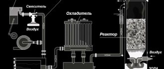
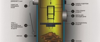
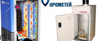
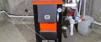
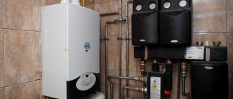
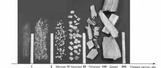
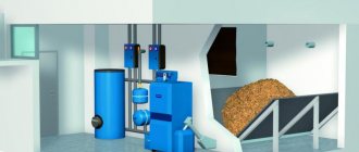
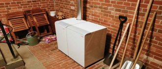
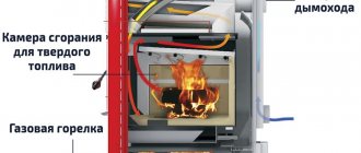
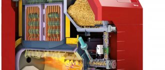
Whatever the type of solid fuel boiler, all have a high level of efficiency, thanks to the design and principle of the device. On this page, we will consider and try to understand how solid fuel boilers work. The main difference between conventional solid fuel boilers and long burning solid fuel boilers is that in the second case, combustion takes much longer due to the combustion principle. So let's look at the principle of operation of solid fuel boilers and how solid fuel boilers work in order to understand how to choose a boiler.
The principle of operation of a long-burning solid fuel boiler.
Typically, these solid fuel boilers operate on the principle of "top combustion". How does a long burning boiler work? Before oxygen enters directly into the furnace, where combustion takes place, it is heated up. It is heated in order to ultimately reduce the amount of combustion waste: soot, ash. Oxygen is supplied not from bottom to top, but from top to bottom. Thus, only the top layer of solid fuel stored in the firebox burns. Due to the fact that the air enters from above, it does not penetrate downward and the combustion process is impossible there. Only the top layer of fuel burns. When the top layer burns out, feed to the bottom layer is turned on. So gradually, as the combustion progresses, the air is supplied lower and lower. Thanks to this approach, the top layer of fuel always burns, and the one below remains intact until it comes to its turn. This allows very economical consumption of fuel and control of the combustion process. It is with this technology that solid fuel burns for a very long time.
Such boilers are not only economical but also environmentally friendly. Of course, provided that fire-resistant building materials are used, which will not only ensure the maximum efficiency of the boiler, insulating heat, but also protect against possible fires.
You can clearly understand how the pyrolysis boiler works from this video:
Classification of combustion devices
1
Combustion devices of BOILERS
A combustion device or furnace is a part of a boiler unit intended for the implementation of thermo-oxidative processes (fuel combustion) in order to obtain high-temperature combustion products. At the same time, the furnace serves as a heat exchange device, in which heat transfer occurs by radiation from the combustion zone to radiation heating surfaces.
By method of burning
fuel, all combustion devices are divided into layer and chamber (vortex). In layered furnaces, solid lumpy fuel is burned in a layer lying on a corresponding support surface (see Fig. 1.1).
By fuel layer condition
furnaces are subdivided into layered ones with a dense suspended layer - a fluidized bed (TKS).
AT chamber flare furnaces
combustion of gaseous, liquid and pulverized solid fuels is carried out with the help of special spraying devices, otherwise called burners.
Fuel combustion in vortex furnaces is carried out in the suspended state of the fuel, which is supported by the set of the chamber shape and aerodynamics of the process.
Layer furnaces,
for combustion of various types of solid fuels are divided into internal and external, with horizontal and inclined grates.
Furnaces located inside the boiler lining are called internal.
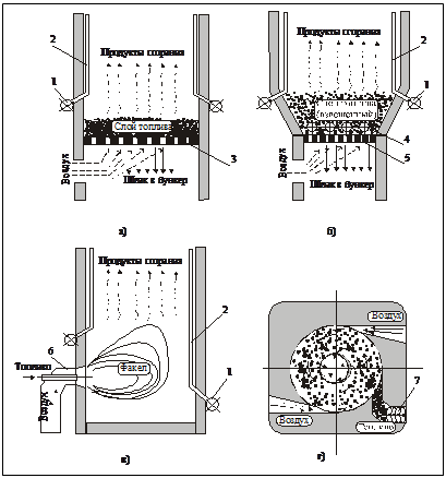
Fig. 1.1. Fuel combustion methods: a - layered (dense layer); b - layered (weighted layer); в - chamber in a torch; d - chamber vortex.1 - collector; 2 - screen tubes; 3 - grate; 4 - submersible heating surfaces; 5 - air distribution grille (VRP); 6 - burner device; 7 - auger for fuel supply
Furnaces located outside the lining and additionally attached to the boiler are called remote.
Depending on the method of fuel supply and the organization of service, layer furnaces are subdivided into manual, semi-mechanical and mechanical.
By hand
furnaces are called in which all three operations - supplying fuel to the furnace, shuraing it and removing slag (focal residues) from the furnace - are performed manually by the stoker. As a rule, these furnaces have a horizontal grate. Such furnaces are usually called manual grate furnaces (RKR).
Semi-mechanical
are called furnaces in which one or two operations are mechanized. Such furnaces include mine furnaces with inclined grates, where the fuel loaded into the furnace manually, as the lower layers burn out, moves along the inclined grates under the action of its own mass. Furnaces with mechanical or pneumomechanical throwers with rotary grates (PZ-RPK).
Mechanical
furnaces are called in which all three operations are mechanized. These include furnaces: with a movable grate cloth (LTSR - belt chain lattice, ChTSR - flake chain lattice, BCR - bottomless chain lattice) and a fixed bed; with a moving bed and a fixed grate - furnaces with a rustling bar (TSP), etc.
1
Date Added: 2016-06-22; views: 7503; ORDER WRITING WORK
Similar articles:
How does a pyrolysis boiler work. The device and principle of operation of the pyrolysis boiler.
The principle of operation of a pyrolysis solid fuel boiler is based on the process of decomposition of solid fuel into pyrolysis gas and coke. This is achieved by insufficient air supply. Due to the weak air supply, the fuel slowly smolders, but does not burn, as a result pyrolysis gas is formed. As a result, the gas combines with air. combustion occurs and heat is released, which heats the coolant. Thanks to this process, there are very few harmful substances in the smoke, and soot and ash are negligible. So in the case of pyrolysis boilers, you can also talk about environmental friendliness.
So, let's take a closer look at the principle of operation of a pyrolysis boiler.
- What is pyrolysis? Pyrolysis is a combustion process under conditions of insufficient oxygen. The result of such combustion is solid combustion products and gas: solid waste is ash and a mixture of volatile hydrocarbons plus carbon dioxide.
- The principle of operation of the gas generator(or pyrolysis boiler), is that such a solid fuel boiler divides the heating process into two processes. First, this is the usual process of burning solid fuel, while limiting the supply of oxygen. When there is a shortage of air, solid fuel smolders very slowly, releasing gas. It limits the oxygen supply, the boiler is very simple, with a mechanical damper, which, depending on the amount of air in the furnace, either opens or closes. In this case, you can manually "turn on the heat" by slightly opening the damper.
- Second part of the combustion process fuel, consists in burning out the volatile waste of the combustion process in the first furnace. In the second furnace, the so-called pyrolysis gas burns out - the result of burning solid fuel in the first furnace.
- Adjustment in this case, as in the case of air supply to the first furnace, it is very simple. The thermostat controls the combustion process and changes the operation of the boiler just as much as necessary to generate the required amount of heat. In principle, it does not differ much from a thermostat for a water heater.
- The efficiency of pyrolysis boilers. By far the most efficient boilers are those in which combustion occurs from top to bottom.Of course, this imposes certain difficulties, for example, in such boilers, forced draft has to be done, because the second afterburner of pyrolysis gas is located under the grate. To put it simply: the fuel is scattered into the waste product of the combustion process - into ash. In this case, gas is formed, which is also afterburned. The result: maximum heat release, with virtually waste-free combustion. Plus, the ash can be used as fertilizer.
The principle of operation of the pyrolysis boiler is designed in such a way that in addition to the most efficient combustion of fuel, we also have minimal waste from the combustion process... The main disadvantage is the price of pyrolysis boilers, but there are actually a lot of positive aspects:
- Minimum waste and minimal cleaning of the furnace, in comparison with other solid fuel boilers.
- Long battery life no additional loads due to economical air supply.
- Automation combustion process. The boiler itself regulates when to increase combustion and when to decrease.
- Large solid fuels suitable for such boilers, since in any case the afterburning of the fuel takes place almost completely.
Method of flaring fuel combustion in the boiler furnace
9) (111 UNION OF SOVIET SOCIALIST REPUBLINS 11/00 WRITING OF THE INVENTION SHCHEYUYUEVas 1 tanovSSSR 979. USSR STATE NOMITTEE FOR INVENTIONS AND DISCOVERIES, p. 1572, Inventor's certificate 9 840582, class R 23 R 21/00, (54) (57) METHOD OF AC FUEL IN THE FURNACE OF THE CAT for a torch of electric current through it, because, with the same frequency of alternating equal to the frequency of the acoustic vibrations of LIGHT COMBUSTIONA when the applied field and the transmitted electric current increase the efficiency, the current of maintaining the back tone of gases in the furnace. 1103040 Circulation 532 Subscribed VNIIPI of the USSR State Committee for Inventions and Discoveries F 113035, Moscow, Zh, Raushskaya nab., 4/5, branch of the PPP FPatent, Uzhgorod, Proektnaya st., 4 The invention relates to energy and can be used in cameras combustion of hot water and steam boilers. There is a known method of combustion in a furnace boiler by supplying fuel and an oxidizer with subsequent ignition of the mixture 1. The closest in technical essence to the invention is a method of flaring fuel in a furnace, a boiler when an electric field is applied to the flare and passing through it an alternating electric current 121. The disadvantages of the known methods are the disadvantages of the known methods. relatively low efficiency. The aim of the invention is to increase the efficiency. This goal is achieved by the fact that according to the method of flaring fuel in the boiler furnace, when an electric field is applied to the torch and an alternating electric current passes through it, the frequency of the alternating current is maintained equal to the frequency of the fundamental tone of acoustic vibrations of gases in the furnace. The drawing shows a boiler in which the proposed method can be used. The boiler contains a flame tube 1 with a jacket 2 and a burner 3. The flame tube 1 and burner 3 are connected to a high voltage source (not shown in the drawing) with an adjustable hour This output signal. During the operation of the boiler, the fuel enters the burner 3. At the same time, 5 the high voltage source is turned on and an electric field is applied to the combustion zone. At the same time, an alternating electric tox flows through the torch with a frequency equal to the frequency of the fundamental O tone of acoustic vibrations of gases in the pile, which can be measured or calculated. The method is implemented in a boiler with a height of 0.237 m and a diameter of a fire tube of 0.068 m. In this case, the same amount of fuel was burned and the same amount of water was heated with the power supply turned on and off. The frequency of the fundamental tone of acoustic vibrations in the furnace was determined by calculation and was 600 Hz for this furnace. At a given frequency of the electric current passed through the torch, the increase in heat was 25-17000 kJ in terms of 1 nm of combusted gas. The voltage and current were 3.7-5.7 kV and 1114 μA, respectively. Hence it follows that the power consumption was only 0.01 of the heat gain. The use of the invention will increase the efficiency of the boiler.
Look
Automation and mechanics of solid fuel boilers.
Despite all levels of control over combustion processes and operational safety in general, solid fuel boilers practically do not contain complex automatic devices. Due to the fact that most often the temperature is regulated by mechanics, there is practically nothing to break in boilers. In addition, the design of the boilers itself is simple and reliable. Therefore, it is realistic to do the installation of a solid fuel boiler with your own hands, but it is better to contact specialists. You can even make a boiler room with your own hands, but why unnecessary problems if you can entrust everything to professionals?
Combustion device (firebox) - this is an integral part of the boiler plant, in which fuel is burned, the combustion products are partially cooled and ash is released. Depending on the method of fuel combustion, furnaces are subdivided into layered and chambered. In layered furnaces, solid lumpy fuel is burned, which is located in a dense layer on a grate blown with air. In chamber furnaces, gaseous, liquid or solid fuel (the latter in suspension) is burned throughout the entire volume of the combustion chamber. Diagrams of different types of furnaces are shown in fig. 16.4.


Fig. 16.4. Schematic diagram of furnaces:
a - layered; b - with a fluidized bed; в - flare; r - vortex; Ι - fuel; ΙΙ - air; ΙΙΙ - flue gases
By the nature of the organization of the combustion process, layer furnaces are distinguished:
with a fixed grate and a fixed layer of fuel on it;
a fixed grate and a layer of fuel moving along it;
a moving grate that transports the fuel layer on it.
Chamber furnaces, in turn, are subdivided into boiling (fluidized) bed, flare and vortex furnaces. In fluidized bed furnaces, fine-grained particles of solid fuel are fluidized by an air flow and, during combustion, randomly move through the volume of the combustion chamber without being removed from it. In flare furnaces, the combusted fuel and the air supplied for combustion form a torch; the gas distribution grille is absent in this case. In vortex (cyclonic) furnaces, by tangentially introducing the air flow into the cylindrical combustion chamber, a swirling stream of reagents (air and fuel in the form of dust, sawdust and husks) is created, which are effectively mixed, as a result of which the fuel burns well.
The furnaces can be located inside the boiler lining (in this case, they are called internal) and outside it (remote furnaces). The thermal power of the internal furnaces is limited by the dimensions of the boiler lining, which is their disadvantage. Layer furnaces are made by hand and mechanized. Manual furnaces with a fixed grate are used in boilers with a steam capacity of up to 1 t / h, the fuel loading into them is periodic. Mechanized layered furnaces with a chain grate are used in boilers with a steam capacity of 10 ... 35 t / h.
The layered furnace with a fixed grate and a fixed layer of fuel on it, has a pneumatic mechanical thrower. It contains a grate of the RPK type with cast iron rotary grates mounted on shafts. With the help of the handle, the rows of grates periodically tilt, and through the cracks formed between them, the slag from the grate spills into the slag bunker. A pneumomechanical spreader with a rotor with blades is driven by an electric motor through a three-stage V-belt transmission, which provides a rotor speed of 500, 600 and 700 rpm.
The layered furnace with a fixed grate and a layer of fuel moving along it under its own weight is intended for operation on a lump or
(16.1)
Heat Q1taken up by water and steam in the boiler can be determined from the equation
(16.2)
Here hne, hnв —
enthalpy of superheated steam and feed water.
Considering these two formulas together, it is easy to obtain a formula for calculating fuel consumption, B:
(16.3)
The value of ηk, taken here in fractions of a unit. According to the formula of the above, the boiler efficiency is calculated according to the data of balance tests (direct balance), which makes it possible to accurately measure the fuel consumption in a steady (stationary) mode of operation. Therefore, boiler testing should be preceded by its long-term operation with constant load, at which the test is carried out. Formula 5, called the inverse balance formula, is used in the calculations of the designed boiler. In this case, each of the qi components is taken according to the recommendations developed on the basis of repeated tests of boilers under conditions similar to the design ones. This formula is used in cases where it is not possible to accurately measure fuel consumption. Modern boilers are quite sophisticated units; their efficiency exceeds 90%.
