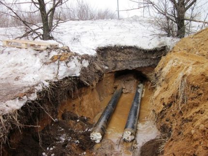
If underground utilities cross a road or railroad track, the dismantling of such objects can be extremely difficult, and often even impossible. To solve the problem, laying pipes by the puncture method will help. This method is much easier and cheaper to implement.
For those wishing to learn how pipes are laid in the ground without disturbing ground coverings, demolishing buildings, moving mobile objects, we will reveal the specifics of the technology. Here you will find out what equipment is used in the course of work, in what way punctures are carried out.
In addition to the title method, we described alternative options for laying pipes in the ground using trenchless technology, attached diagrams, photo selections and video materials.
Hydro-, vibration puncture and punching
Distinguish between hydro and vibration punctures. In the first case, a water jet is used as a tool for pushing through the soil, which, under high pressure, beats from a special tip.
This method is especially effective on loose sandy soils that are easily washed away by the jet. It allows you to make a hole with a diameter of about 50 cm in a minimum amount of time. But the maximum length of the well during hydro-piercing is 30 m.
Vibration puncture, as the name implies, is carried out with the help of vibration exposure. In the device for making a puncture, shock-vibration-indentation installations with exciters of longitudinal-directional vibrations are used.
Static indentation is combined with the impact on the ground of shock impulses from a vibratory hammer. The method is used on water-saturated and low-moisture sandy soils both for laying pipes and for extracting them. The borehole diameter can reach 50 cm, and its length is 60 m.
The punching method is carried out using jacks, like a puncture. But in this case, the pipe is directed into the ground with its open end. In the process of advancing the structure, a dense plug from the soil forms in the pipe, which is then removed.
To perform this type of work, from two to eight powerful (200-400 tons) hydraulic jacks are used, for the operation of which it is necessary to install a thrust wall with a frame and a headrest.

Digging is a trenchless method of pipe laying, which is carried out using special high-power hydraulic units.
During a shift, such a device can go up to 10 meters of soil, and the total length of the well usually does not exceed 80 meters. If it is required to lay a longer route, it is divided into separate sections of no more than 80 meters.
This method also requires the device of the initial and final pit, in which the necessary hydraulics are installed.
Each section is driven twice: in the forward direction and then in the opposite direction. The operator, who is in the pit, controls the operation of the mechanisms and the quality of punching.
Technically, this method is more difficult than a conventional puncture, but it can be used on almost any soil. The diameter of the structure can be up to 172 cm. Cores formed inside the pipe can be taken manually or mechanically.
Trenchless pipe laying - types and methods
Existing technologies make it possible to lay pipelines at great depths when laying new lines or inside channels of old pipes, sometimes with their destruction.
Reconstruction and replacement of the pipeline by the rehabilitation method
Remediation is the method of wiring lines using old communications, while two technologies are distinguished:
- Relainig... This rehabilitation method is used if the old pipeline is kept and it serves as a shell for the new pipeline, which is pulled inside.
- Renovation. This technique consists in the fact that when a new line is laid, the old line is destroyed - it is cut along with roller or fixed knives and the expander increases the radius of the circumference of the passage channel, pressing the remnants of the shell into the ground.
Relining technology
Relining is the most cost-effective method in a situation where an outdated line is replaced with a modern plastic (low-pressure polyethylene HDPE) of a slightly smaller diameter. The HDPE pipe production technology allows its connection by welding; for this, the industry produces a wide range of devices that carry out leveling processing, heating with a disk iron and welding of ends. When carrying out work on broaching, the length of the HDPE line can reach 700 meters; in the process of feeding, pipes (10 - 12 m) are welded to the surface with special expensive electronic units suitable in size.
Quite often, it is necessary to broach a polyethylene line of a slightly larger radius along the old steel pipeline - for this, broaching technologies are used with a special expander knife, which is used to cut the pipeline along. The work carried out consists of the following stages:
- A worker and receiving pits of the required size (depending on the depth of the pipeline and the dimensions of the machines) are dug along the edges of the site to be replaced to accommodate engineering equipment.
- With the help of a special mechanism of hydraulic jacks, metal rods are twisted and fed into the channel, pushing them until they exit the line in the receiving pit.
- A plastic pipeline is connected to a metal rod through fasteners located on a special tip in the form of an expander knife.
- The hydraulic machine pulls in the opposite direction while slitting the steel pipe shell. In this case, the rods, as they are removed, are unwound and removed from the pit.
Benefits of the puncture method
The demand for the puncture method is explained by its significant advantages over other options for performing this type of work. For example, a puncture is available at any time of the year, the high or low temperature of the outside air and soil does not matter much.
One of the advantages of the guided puncture method is that work can also be carried out in areas with an elevated water table.
The operation of the unit does not require the use of bentonite mud, the supply of water or drilling mud to the well. It is a compact and powerful unit that is equipped with a reliable electrical safety system. It is not difficult to deliver and install it. At the same time, the compact size does not prevent the device from working with high power ratings.
Trenchless pipe laying methods such as guided puncture can be successfully applied in both summer and winter.
The work time is also shorter than with other methods. Even if in the area where the puncture is performed, there is an increased level of groundwater, there is no need to carry out measures to drain water from the site.
During the passage of the expansion cone, the walls of the trench are also compacted, so no additional work is required in this regard.

Benefits of trenchless piping
The most common method of laying pipeline structures is considered to be trenching. However, this installation option has its drawbacks, which include:
- digging up the soil entails a violation of the fertile layer;
- elimination of trees and other plantations;
- high cost of installation work;
- long preparatory stage.
Note! When the canal for the pipeline passes through the road surface, destruction of the asphalt cannot be avoided, therefore, after the work, the road will have to be reconstructed. In addition, if this is a fairly busy section of the road, then it can be difficult to overlap. In such cases, trenchless (closed) laying of communication comes to the rescue.
The trenchless method has the following advantages:
- less material resources are required to carry out work;
- high speed of installation;
- the minimum number of workers;
- harmless to the environment;
- the possibility of laying pipes all year round (installation of pipes in an open way in winter is difficult because of the frozen soil);
- work safety.
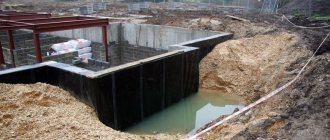
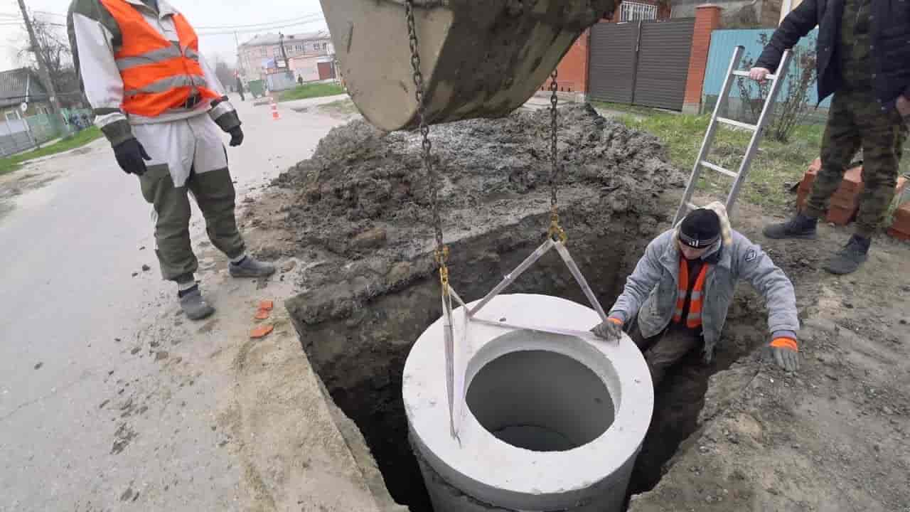
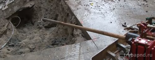
![]()
For trenchless pipe laying, it is enough to dig a small pit
If the installation of the pipe is carried out on a small section, for example, under the road surface, then all the work can be performed without the use of special equipment. This wiring is quite simple. It requires a cylinder of the required diameter and a stackable rod. Thanks to such a device, it becomes possible to remove the earth manually, however, before that, work is carried out to dig out small pits on both sides of the road. For closed installation on large areas, special machines and units are used.
Performing a puncture on different objects
The complexity and speed of this type of work largely depends on the conditions, i.e. on the terrain and characteristics of the object under which the puncture is performed. Drilling under a railroad bed usually requires a fairly serious design. First, you need to coordinate drilling with a number of railway services.

Using the guided puncture method within the city limits the integrity of road routes to minimize costs and not disrupt traffic
In Russia, you need to contact the departments of ECH, ShCh, RCS NODG, PCh and other services of Russian Railways. It is mandatory to draw up contracts for technical supervision, as well as for the installation of safety packages. All executive documentation must be agreed upon and provided to the railway authorities.
A package of documents is transferred to the distance of the path at the end of the cycle of pipe laying. In cities, a puncture under the road is in great demand when laying new communications, especially in places with historical sights.
The method allows not only to keep the usual traffic on the roads, but also to prevent the destruction of the old pavement, when it is necessary to lay pipes under such sections.
The restoration of such an object can be difficult, and sometimes impossible. In cottage settlements, the laying of communications by the puncture method allows you to perform all work with minimal damage to ready-made objects: roads, fences, etc.
Trenchless laying of pipes for engineering communications is most often used under natural and artificial obstacles - road and railways, existing buildings and communications networks, including during the reconstruction of enterprises.
For the production of work, one or another method of laying protective pipes-casings is chosen, which is a complex and time-consuming technological operation when arranging intersections-transitions under obstacles. The main methods include:
a) pipe laying without soil extraction (puncture): by static penetration by hydraulic jacks and pulley systems; using shock and vibration devices;
b) trenchless pipe laying with development and extraction of soil; with continuous excavation and introduction of the pipe being laid (drilling); by periodically extracting soil core from the pipe being squeezed through.

-When choosing a method of laying a casing pipe, the diameter and length of the pipe to be laid, soil and hydrogeological conditions, the purpose and technical condition of ground structures along the crossing route, operational requirements for the crossing under construction (strength of the laying, requirements for insulation, etc.) are taken into account "economic feasibility ( Table 5.2).
Puncture (Figure 5.3) is usually carried out laying pipes with a diameter of 50 to 400 mm and more (Table 5.3) in loamy and clayey soils of any moisture. In sandy soils, this method is less effective. The depth of laying is limited by the minimum distance from the surface to the pipe to be laid, equal to its five diameters. Punching pipes are laid using jacks, soil-laying machines and pneumatic punches, winches, tractors, pipe-layers and bulldozers.
Construction machines are used to puncture pipes under embankments, the slope of which is not subject to special requirements, mainly for cable networks. To perform a puncture on one side of the embankment, a site is planned for placing the pipe and machine. The puncture is carried out by transferring the force from the "machine" directly to the end of the pipe or through a nozzle.
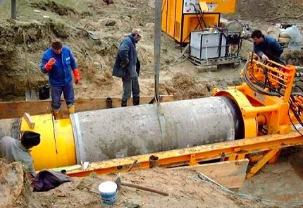
The most common pipe puncture using ground-piercing jacks. To do this, a working pit is torn off, in which a jack installation with a section of the pipe to be laid (usually 6 m long) is placed. The high pressure hydraulic pump is located on the edge of the pit (fig. 5.3).
The pipe is laid by transferring force through the headgear with push-on extension pipes 1-4 m long, ramrods or clamping clamps. The movement of the pipe is carried out cyclically by alternately switching the jacks for forward and reverse motion. With a straight stroke, the pipe is pressed into the ground for the length of the jack rod stroke. After the stem is returned, the branch pipe is changed to another, doubled length, and the indentation cycle is repeated until the pipe link is punctured. Subsequently, a new pipe link is installed and all operations are repeated until the end of the puncture of the required length. A puncture is also performed using a cleaning rod.
The most productive jacking units of Glavmosstroy and GPU-600 (Fig. 5.4) The fundamental difference between these units is the presence of a movable thrust plate, which is moved by jacks after the pipe being laid after each indentation cycle until the pipe section is fully penetrated into the ground. After pressing the pipe section into the ground, the movable stop, the slide with jacks and the pressure plate return to their original position.
To puncture with pipes up to 800 mm in diameter, the Ukrorgtech-stroy tool feed mechanism with a pushing force of up to 2000 kN can be used, complete with horizontal drilling units of the PM-800-1400, PM-800-1600 and Zaporozhye type. The use of a feed mechanism complete with these horizontal drilling rigs provides their versatility, i.e. the ability to drill pipes with a diameter of up to 800 mm by the puncture method, and with pipes larger than 600 mm - by the horizontal drilling method. When laying pipes using the puncture method, the feeder can also be used independently.
For long-length puncture with pipes up to 800 mm in diameter, jacking machines can be used, consisting of several jacks and creating forces up to 10,000 kN and more.

When reconstructing enterprises for puncturing pipes with a diameter of up to 500 mm in disconnected, sandy and floating soils, it is effective to use vibration-piercing installations; for puncture in soils of I, II and III categories with the presence of stone, brick, fragments of wood and other construction waste pipes with a diameter of up to 400 mm - pneumatic punches. A positive quality of vibro-piercing installations and pneumatic punchers is the possibility of their use for replacing old pipes for underground laying. In installations for vibration puncture (Fig.5.5) vibro-impact devices are used that create longitudinally directed vibrations. The vibro-shock device is fixed at the rear end of the pipe and installed on a trolley with a rail track. A tapered tip is welded to the bottom-hole end of the pipe. Vibration puncture is carried out under the action of shock impulses in combination with static indentation by a winch mounted on a trolley, which transfers the force to the pipe through the load chain hoist.
To the rubber hose from the compressor, it reciprocates and strikes the front inner end of the housing, driving it into the ground. The reversing device allows you to change the direction of the machine by changing the direction of the blows. The set of pneumatic punches includes reamers for punching large-diameter wells. The reversible work of pneumatic punches is carried out without expanders.
Technological operations “when punching wells with pneumatic punches (Fig. 5.6) begin with its penetration into the ground from the outlet pit in the direction of the receiving pit. When moving, the pneumatic punch, with its conical front end, compacts the soil, pushing it to the sides, and forms a well. To perceive reactive forces at the time of starting the machine from the pit, starting devices are used that create friction forces on the body of the pneumatic punch or push the machine to the bottom. In addition, to facilitate the introduction of the pneumatic punch into the ground, the launch is carried out at a reduced pressure (0.3-0.4 MPa) of compressed air.

In addition to punching wells, pneumatic punches can be widely used when performing other technological operations: driving steel pipes (casings), tightening asbestos-cement pipes and extracting pipes from the ground (Table 5.5). pipes and hammering it into the ground. The front end of the pipe is closed with a tapered tip.
When replacing pipes, a new section of the pipeline with a pneumatic punch installed in the rear end is connected to the removed one, and the old pipe, as it exits into the receiving pit, is cut off and removed.
Punching steel pipes with a diameter of 500-2000 mm or reinforced concrete collectors of round, square or rectangular cross-section at a distance of up to 80 m is carried out by push-on pump-jack units connecting 2, 4, 8 or more hydraulic jacks. The jacks are mounted on the frame; for their stop there is a special thrust wall, consisting of piles and two rows of beams.

For punching pipelines, installations with mechanized development and soil removal such as SKV Glavmosstroy and PU-2 designed by TsNIIpodzemmash are most effective (see Table 5.3). The PU-2 installation consists of four parts: a power unit, a working body, a device for transmitting pressure forces and a knife section (Fig.5.7). Technological operations using the PU-2 installation are performed in the following sequence. The first link of the casing with a knife section installed at its end and a system of deflecting rollers is laid on the guide frame placed in the pit. After checking the correct direction of the gasket, the working body is introduced into the plane of the link and the ropes are stored. Then the hydraulic jacks are turned on, which push the main pressure crosshead forward until it touches the end face of the casing link being laid. With further movement of the traverse, the front end of the casing is slightly pressed into the ground. Then the supply of the casing is stopped and the working body is pulled up with the help of the working rope until the cutting edge of the bucket touches the bottom. Further pulling the rope is accompanied by moving the working body forward and turning the bucket from top to bottom.

The cut soil falls into the lower part of the casing cavity.Slowing down the working body and pulling up the traction ropes, the working body is retracted from the face approximately 1-1.2 m in diameter.
In this case, the cut soil will move by the bucket along the casing at the same distance. Then, the traction rope is loosened and the retractor springs are allowed to turn the cutting device to its original position, that is, from the bottom up. Pulling up the traction rope again, the soil development cycle is repeated. After repeating several cycles, the working body is removed from the face, while the soil accumulated behind the scraper valve is carried out into the receiving chute, which, together with the soil, is lifted by a crane outside the working pit and emptied. After returning the working body to the cavity of the casing being laid, the casing is fed again and the bottom soil is worked out.
Punching pipes can be done using pneumatic punches. In this case, the pipe (casing) is penetrated by the open end into the ground under the influence of an impact load. The soil is removed from the inner cavity of the casing by a self-propelled capsule driven by a reversible pneumatic punch. The capsule is a piece of pipe with cutouts to reduce mass and facilitate soil unloading. For punching pipes with a diameter of 530-1020 mm to a length of up to 50 m in cohesive, sandy and quicksand soils, the UVG-51 vibro-impact unit is also used (see Fig. 5.5). To vibrate the pipe at the bottom hole

at the end, a sickle-shaped pad is welded to provide a gap (10-15 mm) between the well and the pipe, and two symmetrically located lateral windows are cut in the back of the pipe to remove soil. The soil from the pipe is selected by a vibroimpact thief, introduced into the face with a vibrating hammer and moved after the extraction of the soil by means of a rope to the unloading windows. From the bailer, the soil is poured out under the influence of vibration into the unloading windows at the bottom of the trench.
The laying of pipes with a diameter of 1220 mm for a length of up to 60 m in dry and moist soils of groups I-III is performed using the U-12/60 installation. The installation contains a head with a shuttle installed in the bottom hole of the pipe, a hydraulic jacking drive that develops a pressing force of up to 3400 kN, a pumping station, a winch and a thrust shoe (Fig.5.8).
For trenchless pipe laying using the U-12/60 installation, a pit 13 m long, 3 m wide and 0.1 m deep below the design level of the base of the pipe to be laid must be prepared. In the rear part, the pit should be widened and deepened for the installation of a lining made of beams or sleepers and the installation of an inventory stop shoe.
The work of the U-12/60 unit consists in periodically pressing the pipe to be laid to the length of the jacks stroke (1000 mm), followed by the extraction of the shuttle from the pipe to be laid and unloading it. After each pressing cycle, operations are performed to remove the pressure pipes, clean the place where the shuttle is installed in the head with the help of several moves of the shuttle to the bottom, build-up or install longer pressure pipes for subsequent pressure. The filling of the shuttle with soil is ensured by pressing the pipe with hydraulic jacks when the shuttle is wedged in the head of the pipe being forced through. The shuttle is unloaded into a dump or transport.
{AF template = default colorize = ee77bb width = 100% bgcolor = 77ee44 ratio = 30}

The sponsor of this material is the research and production complex plant of drilling equipment Gidrophobe. The main activity of the enterprise is the implementation of work on the laying of underground communications by the trenchless method using the technology of horizontal directional drilling (HDD), as well as the development of the introduction of energy-saving technologies.
Representative office in Moscow: 117628, Moscow, st. Kulikovskaya, 1, office 1, near the metro station Bulvar Dmitry Donskoy Telephone in Moscow
Tel./fax: (8639) 25-96-50, 25-97-16, 25-97-23
{/ AF}
Assessment of alternatives
In addition to the controlled puncture method, there are other options for arranging communications in the soil without trenching. Sometimes the alternative may be more acceptable than a puncture, it all depends on the specific situation.
Horizontal directional drilling, which is also called oblique direction, is used for laying pressure and non-pressure pipelines. Drilling in this way is performed from the surface of the earth. The diameter of the hole should be taken 30-50% larger than the dimensions of the pipes that are supposed to be laid in it.
The hole is not expanded immediately, but in several stages. In this case, a bentonite solution is used, which is mixed with the loosened soil and facilitates its removal from the trunk. In addition, this working fluid is used to cool the drilling tool, and then it forms a layer on the walls of the shaft that protects them from destruction.
A sludge pump is used to pump out the spent bentonite solution. After pumping out, the unnecessary solution must be taken to a landfill for further disposal. If the work is done correctly, the result is a clean well with strong walls.
Drilling rigs for this type of work have different characteristics such as torque and pulling force. The length of the pipes that will be laid in the soil layer, which can reach 1000 meters, depends on this.
The permissible pipe diameter is 120 cm. Both metal and plastic pipes can be laid by horizontal directional drilling.
Drilling is performed along a pre-calculated trajectory, the movement of the drilling tool is controlled using a location system. The collaring angle can vary between 26-34 degrees.
Another important indicator when using HDD is the bending of the rods, which can be 6-12%, it depends on their type. Another popular trenchless pipe laying technique is auger drilling... For its implementation, a special hydraulic unit is used, which acts as a jack.
First, start and finish pits are made. The depth of each of them should be one meter deeper than the level of the pipeline. A hydraulic installation is lowered into the starting pit, which rotates the auger and punching pipes. As a result, part of the soil is removed and a pipe hole is obtained.
Then pipes, cases, etc. are installed inside. The maximum laying length is usually only 100 meters, but the diameter of the communications can reach 172 cm, the indicators largely depend on the type of soil on which the drilling is carried out.
The method of punching steel cases is often used if it is necessary to lay pipes or cases of large diameter using trenchless methods.
To control the work during auger drilling, a laser is used, which ensures the correct angle of inclination of the drill, and also allows tracking the direction of drilling with high accuracy. After the auger reaches the finishing pit, it is removed from the resulting well in the reverse order.
Microtunneling Is a high-precision method of trenchless laying of communications, which is performed using a special tunneling shield.
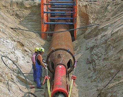
A high power jacking station is used to move the device. It affects the column of reinforced concrete pipes, which are attached to the shield. Gradually, the length of the well increases, so the length of the column is increased by building up reinforced concrete structures.
For the laying of reinforced concrete and steel pipes, the microtunneling method is used. It is performed using a special tunneling shield that loosens the soil
This method also requires preliminary preparation of two pits, the distance between them can vary within 50-500 meters.The jack installation must be lowered into the starting pit to a depth that corresponds to the level of laying communications. If the borehole length exceeds 200 meters, an intermediate jacking station is usually used.
The tunneling shield loosens the soil, which is washed out with water or bentonite solution flowing through the supply lines. The spent liquid, mixed with soil particles, moves to the sump along the drain lines. After the tunnel shield enters the finishing pit, the work can be considered completed.
Trenchless methods of laying communications are carried out using special high-power equipment. Accurate adherence to technology will ensure a reliable well
The equipment is disassembled and removed. Using the microtunneling method, you can install not only reinforced concrete, but also steel pipes. To control the correctness of the work, a navigation system is used, which consists of a laser, a target and a measuring wheel.
For long sections (more than 200 m), an electronic laser system is considered effective, equipped with a hydrostatic level, which gives accurate information about the depth of pipe laying, regardless of the air temperature inside the structure.


Laying steps
Sewerage lining by the puncture method is a procedure performed in several stages:
- preparation of the site for equipment. Its size is 10 × 15 m;
- installation of a pilot rod that plunges into the ground at the point of entry of the drill head;
- drilling a pilot well. This is the main stage of work. A well is made with a given configuration, its diameter is 100 mm. Trajectory control is carried out every 3 m of length;
- removing the drill head and expanding the well by pulling the rimmer. This is a tool that is installed on a coiled rod and pulled with force in the direction opposite to the penetration of the pilot well;
- behind the rimmer, a string of pipelines is attached, which, immediately after the expansion of the well, is pulled into it in the direction of the drilling rig.
A sewer puncture device requires constant monitoring of the trajectory. This is done by the operator, who observes the progress of the work on the display of the receiver. The signal goes to it from the sensors of the drill head. If it is necessary to change the trajectory, it instructs the driller to stop the feed and sets the desired angle of rotation. At any of its value, the head is rotated only clockwise so as not to weaken the connection of the drill rods.
Varieties
Sewerage by the puncture method is an effective and promising technology. Since its inception, three options for performing work have been developed:
- hydro-puncture;
- vibration puncture;
- punching.
Each of these techniques is designed to work under specific conditions. For example, the hydraulic method is good in clayey viscous soils, the vibration method is more effective in dense rocks with numerous rock inclusions. Punching is used on soft soils that do not require significant efforts to drill a well.
Any technique requires a significant axial thrust in the direction of penetration. Powerful hydraulic jacks are used to create it. The boom axle load is large - from 30 to 400 tons, which provides an efficient and quick solution to the problem.
Also read: Do-it-yourself sewer drain - drainage system, features, overview
Advantages and disadvantages
The sewerage device using the HDD method has a number of advantages:
- the costs of laying the network are reduced;
- the technology is less laborious than the traditional technique;
- line construction time is reduced by about 30%;
- it is not required to restore the landscape, elements of surface improvement;
- there are practically no restrictions on the place of work.It is possible to lay on the territory of historical monuments, industrial enterprises, in a dense building area;
- the fertile soil layer is not removed and does not deteriorate;
- during the execution of work, you do not have to block the movement of vehicles, stop production or accept other restrictions.
Disadvantages of HDD technology:
- the technique is not suitable for creating extended wells or for laying pipelines at great depths;
- the maximum length of one line is 300-400 m. If a more extended system is needed, it will be necessary to make intermediate pits and pass through repeated wells.
Certain difficulties arise if a gravity sewage system is made using the HDD method. To do this, it is necessary to provide a height difference between the point of entry and exit of the well. If a pipe with a diameter of 160-200 mm is used, a slope of 8 or 7 mm is required for each meter of length. For a line with a length of 400 m (maximum), the height difference will be 3.2 m. In addition, it becomes impossible to avoid obstacles in the vertical plane. If large inclusions appear on the path of the well, it will be necessary to make a horizontal detour without changing the set angle of inclination. This may require longer piping lengths, which will increase the cost and time to assemble the system.
The subtleties of choosing the right method
The method of laying communications using horizontal drilling is chosen at the design stage of a specific process. If trenchless pipe laying is carried out as part of the construction of an object, for example, a residential building, then the work may become part of a general construction project.
When designing, the following information is taken into account:
- the length of the communications that must be laid in a trenchless way;
- diameter of the case or pipe;
- the material from which the communications are made;
- the depth at which the pipes must be laid;
- type of pipeline (pressure or gravity);
- the ability to install starting and finishing pits of suitable depth;
- access roads to the work site;
- the presence of a sufficiently spacious area for storing materials, equipment, etc.;
- groundwater level;
- other geological features of the site;
- plan of the location of the communications already available on the site.
During the construction process, it is sometimes necessary to change an already drawn up project. This may be due to a desire to cut costs by using, for example, plastic pipes instead of steel ones. In addition, the plan for the location of underground utilities at the facility is not always accurate enough.
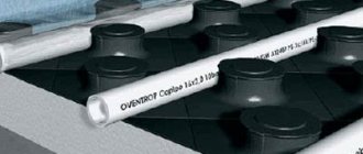
The diameter of the pipe is one of the indicators that are taken into account when choosing methods for trenchless laying of communications. The well should be slightly larger
When performing work, such unaccounted pipes or cables may be found. All these points may require changes in the project, and this may affect the decision on the method of drilling.
If the depth of the laying of communications is small, there is a danger of subsidence of the upper soil layer, especially if bentonite mortar was used during drilling. In such cases, it is better to give preference to horizontal auger drilling.
Very often, the drilling method is determined by what kind of equipment is at the disposal of the organization executing the order.
For example, if builders have jacks or a horizontal directional drill, it will be preferred over the puncture method. Most often, such changes are dictated by considerations of economic benefits.


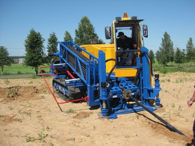
HDD drilling
Trenchless laying of pipes and gas pipelines, as well as other services related to drilling, have long become common practice, because it is an economical, fast and modern way of conducting communications. The rapid development and improvement of trenchless technologies led to the formation of several branches in HDD techniques.
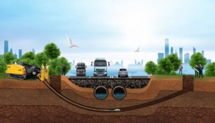
A distinctive feature is the absence of trenches in the working areas from start to finish. Digging ditches, their arrangement, restoration of structures, paths and green spaces after the completion of the work - all this is in the past. Today the world chooses HDD (Horizontal Directional Drilling) technology.
Conclusions and useful video on the topic
The process of operation of the installation for performing a guided puncture is clearly shown in the video:
A guided puncture is a highly accurate and relatively inexpensive way to lay communications under a road or other object. At the same time, it is important to correctly design all work and strictly follow the technology.
Would you like to report interesting facts related to pipe laying using puncture technology? Do you have any questions while reviewing the information provided? Please write your comments in the block below the text of the article.
Special equipment
Trenchless laying of a water supply system implies the use of special equipment and machines. Without it, it is impossible to drill a hole, for example, under a motor road (except for external digging).
Thanks to the use of special equipment, work can be carried out at any time of the year with any type of soil.
Use cases and types of equipment:
- Pump and jack unit - allows you to make a well, bypassing all obstacles. The kit should include a hydraulic station, expander, rods and cutting heads.
- Hydraulic station - a device that provides a power effect using a hydraulic cylinder. Average capacity - 36 tons.
- For hydro-punctures, special devices are used that beat with a powerful directed stream of water. It is used on sandy soils. With the use of such equipment, it is possible to lay pipes with a diameter of up to 50 cm. The length of the pipeline is limited to 30 m.
- Vibration equipment works on the punching shear principle. The installations used in this method have a shock-vibration-pressing principle of operation. In this case, the diameter of the pipes is the same as in the case of hydraulic punctures. But the length of the well is doubled (60m).
- Additional equipment is also used. These can be machines with manipulators, welding, generators, mortar mixing units.
Features of the operation of various installations
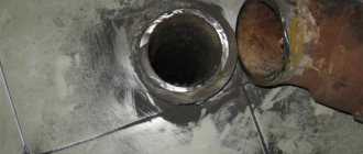
|
| Pneumatic punches of various diameters, type "Mole" |

- Installation GPU-600... When laying pipes with a diameter of 104 to 630 mm, the length of which is up to 80 m, by puncture, on soils of groups I-IV (without large solid inclusions), we use the GPU-600 installation. Its principle of operation is called "walking jacks". First, using hydraulic jacks of 1.2 m (rod stroke length), the workers push the movable pressure plate with the pipe, turning on the oil station. After completing the working cycle with the return of the jacks, the released movable cycle is pulled up following the pipe being laid. These operations are repeated until the first link is embedded in the ground. Then the slide with jacks, the movable stop and the pressure plate return to their original position. After that, we mount the next section of the pipeline and the process is repeated.
- Installation of Glavmosstroy. Pipes with a diameter of 209 to 426 mm in soils of groups I – IV (regardless of moisture content) for a length of up to 45 m are expedient to be placed using the Glavmosstroy installation - it works on the same “walking jacks” principle as the GPU-600.
- Ground punchers and pneumatic punches types IP-4605, PR-400 (or SO-134), PR-60 (or SO-144) and IP-4603 are used by us for laying pipes with a diameter of 63 to 400 mm by a closed method. Pneumatic punches of the "Mole" type allow you to create wells of any kind (open / closed, inclined / horizontal) with sealed walls up to 40-50 m long. its working body, thus driving it into the ground.
- Hydro-puncture. Using the kinetic energy of the water flow, we can pierce pipes using the hydro-piercing method. At the same time, a stream of water coming out of a special nozzle on the front of the pipe blurs a hole up to 500 mm in diameter. Pipes are laid in it. The water consumption is calculated taking into account the pressure, the speed of the stream and the type of soil.This method has its own characteristics: the work is simplified and the rate of well formation increases to 30 m / shift, but deviations from the design axis are possible and the length of penetration cannot exceed 20-30 m.In this case, the working conditions themselves become more complicated - the working pit becomes contaminated ...
The preparatory stage is the coordination of the GNB puncture at the site.
1.1. The customer, before the start of work related to the laying of the GNB pipeline, transfers according to the documents to the direct performers the sections of the underground passages, which are fixed with geodetic marks with the required number of benchmarks within the boundaries of the territory of the work being performed. The axis of the track during its drawing in nature is reinforced with special signs attached to permanent objects.
Three days before the start of work using the GNS technology, the customer invites representatives of organizations that operate the facility and agrees with all owners of communications and structures on trenchless areas that are in the work area.
1.2. The contractor carries out a control inspection of the working site for the presence of risk, or rather, its absence, for example, signs to the underground cable, manhole covers, distribution cabinets, water or gas meters, external communications near the objects. Conducting protective actions, if they are provided for by the project, as well as clarifying the design profile of well drilling.
1.3. Purchase of pipes intended for HDD, the diameter indicated according to the scheme. For laying a pipeline using the HDD method, polyethylene pipes are purchased with a blue stripe for water supply systems or pressure sewerage, or without technical strips, with a thickened wall for laying a cable using the HDD method underground, since the pressure from the outside increases. Insulating properties will be lost if the pipe breaks.
You can purchase a pipe for laying a cable using the HDD method on our website by sending an application. We will call you back, or you can call by phone
Puncture technology
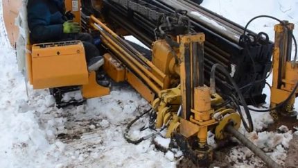
The puncture of the soil under the road is carried out using special equipment. The drilling rig allows you to quickly stack the cases.
In order for the pipes to pass freely into the ground, a bentonite solution is used. It plays the role of a lubricant and eliminates overheating of the drill.
Thanks to the installation, it is possible to puncture the soil under the road and carry out engineering networks when the length of the pipeline is from 2 to 50 meters. The diameter of the pipes used can vary from 16 to 320 mm.
Depending on the power of the drilling rig, it is possible to walk up to 50 meters per day.
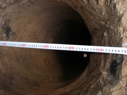
Starting pit for puncture by GNB method
4.1. The depth of the starting pit is determined taking into account the distance from the axis of the pipeline to the bottom of the mine. It all depends on the design of the butt joints and the rig.
4.2. In free areas, it is better to design the starting pit with a rectangular outline. Then, if necessary, it will be possible to increase the length of the installation sections of the pipeline.
4.3. The foundation of the pit must be planned according to the slope of the future well. It is necessary that the base is strong enough to avoid equipment subsidence. The base under the drilling rig is made of crushed stone of fraction 25-70, the thickness of which is from 15 to 20 cm. Then the base is compacted and the road slabs are laid. If the pit is short, then 2 pieces, and if it is long, then 3 or it is filled with concrete.
4.4. When drilling, there is almost always the possibility of flooding the foundation pit. Therefore, during the construction of the starting pit, a pit is made to install a water pump to pump out water. This will keep the bottom of the excavation dry at all times and able to withstand the load. The pit is usually located in front of the pit on the right side.This location is determined by the slope of the base of the pit, which will allow water to be diverted from the cuttings accumulated to the left of the rig.
Description of horizontal directional drilling HDD
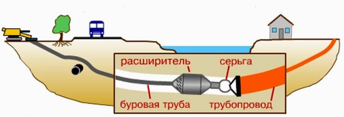
The HDD technique involves drilling a well with a subsequent increase in its width. The horizontal directional method of work is carried out by a drilling rig with a working head. A flexible rod is connected to it, which allows you to change direction to prevent the mechanism from meeting obstacles in the thickness of the soil masses.
If it is necessary to increase the width of the well, then instead of the bit tip, an expander is installed. The technology of laying communications by the method of horizontal directional drilling ends with the process of pulling the pipe. After fixing the communication network on the rod provided for this purpose, the pipe is retracted by installing the HDD into the drilled hole.
Guided puncture
Before performing the work, a study of the soil section is carried out where the puncture will be carried out. Then the project is created. Drilling is carried out in accordance with the planned plan, where the trajectory of the drill is marked.
The machine is supplied with a special blade equipped with a cutting edge. There is also a built-in probe to monitor the movement of the drill. It also allows you to obtain the necessary information about the accuracy of the drilling rig.
To exclude shattering of the borehole walls, a special bentonite solution is used.
Equipment of production sites for HDD puncture under the road.
2.1. The area where the pipeline will be laid using the HDD method is usually located on both sides of the crossed obstacle and is divided into two separate construction and installation sites.
They are conventionally named:
- site No1 of the working (starting) pit and drilling rig
- site No2 of the receiving pit
2.2. Both areas must be cleaned and leveled without fail.
2.3. The starting pit is most often equipped on the side of the well, where it is more convenient to drive up and there is enough space for organizing a construction site.
2.4. In order to organize the transportation of equipment and goods, temporary drive tracks are brought to the assembly sites for puncture using the GNB method. At the stage of arrangement, the planning of the construction strip is carried out. At the same time, various depressions are filled up, the relief is leveled, and the hillocks are cut off. Earthworks are carried out by the Contractor.
2.5. The assembly site is a receiving pit, the dimensions of which will be 3000.0 x 3000.0 x 5000.0 mm.
Puncture machines for difficult soils
Laying pipes in quicksand, incoherent sandy loam and sandy soils, it is possible to speed up the process by means of vibration puncture. In special installations of this method, exciters of vibrations directed longitudinally are used.
Vibration puncher pipes up to 500 mm in diameter are laid for a maximum length of 35 to 60 m, while the penetration rate is up to 20-60 m / h. In the same way, you can extract pipes from the ground.
Focusing on greater efficiency, we most often use installation UVVGP-400 designs of VNIIGS. The principle of operation is as follows: a casing with a tip on one side, the other side is placed in the shock part of the vibratory hammer. Obeying shock impulses, reinforced by static indentation with a loading chain hoist, the pipe moves in the ground.
For the implementation of the puncture, we can also use a vibration shock UVG installation designs MINHiGP them. Gubkin. It is suitable for laying by vibration-impact punching of a casing from 530 to 1020 mm in diameter, with a normal puncture - for pipes 530 mm in diameter.