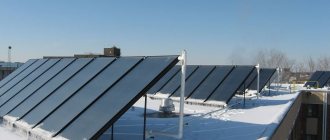
The purpose of the Potapov vortex heat generator (VTG), made by hand, is to obtain heat only with the help of an electric motor and a pump. This device is mainly used as an economical heater.
Vortex heating system device diagram.
Since there are no studies to determine the parameters of the product depending on the power of the pump, approximate dimensions will be illuminated.
The easiest way is to make a vortex heat generator from standard parts. Any electric motor is suitable for this. The more powerful it is, the more water it will heat up to a given temperature.
The main thing is the engine
You need to choose a motor depending on what voltage is available. There are many circuits with which you can connect a 380 Volt engine to a 220 Volt network and vice versa. But that's a different topic.
The assembly of the heat generator is started from the electric motor. It will need to be fixed to the bed. The design of this device is a metal frame, which is easiest to make from a square. The dimensions will need to be selected locally for those devices that will be available.
Drawing of a vortex heat generator.
List of tools and materials:
- angle grinder;
- welding machine;
- electric drill;
- set of drills;
- open-end or spanner keys for 12 and 13;
- bolts, nuts, washers;
- metal corner;
- primer, paint, paint brush.
- Cut squares with an angle grinder. Using a welding machine, assemble the rectangular structure. Alternatively, the assembly can be done using bolts and nuts. This will not affect the final design. Choose the length and width so that all parts fit optimally.
- Cut out another piece of square. Attach it as a cross member so that the engine can be secured.
- Paint the frame.
- Drill holes in the frame for the bolts and install the motor.


Installing the pump
Now you will need to pick up a water pump. Now in specialized stores you can purchase a unit of any modification and power. What should you pay attention to?
- The pump must be centrifugal.
- Your engine will be able to spin it.
Install a pump on the frame, if you need to make more cross-members, then make them either from a corner or from strip iron of the same thickness as the corner. It is hardly possible to make a coupling sleeve without a lathe. Therefore, you will have to order it somewhere.
Diagram of a hydro-vortex heat generator.
Vortex heat generator Potapov consists of a body made in the form of a closed cylinder. At its ends there should be through holes and nozzles for connection to the heating system. The secret of the design is inside the cylinder. The jet should be located behind the inlet. Its hole is selected individually for this device, but it is desirable that it be two times less than a quarter of the diameter of the pipe body. If you do less, then the pump will not be able to pass water through this hole and will begin to heat up itself. In addition, internal parts will begin to intensively collapse due to the phenomenon of cavitation.
Tools: angle grinder or hacksaw for metal, welding machine, electric drill, adjustable wrench.
Materials: thick metal pipe, electrodes, drills, 2 threaded nipples, couplings.
- Cut a piece of thick pipe with a diameter of 100 mm and a length of 500-600 mm.Make an external groove on it about 20-25 mm and half the thickness of the pipe. Cut the threads.
- Make two 50 mm long rings out of the same diameter of the pipe. Cut an internal thread on one side of each half ring.
- From the same thickness of flat metal as the pipe, make caps and weld them on the side of the rings where there is no thread.
- Make a central hole in the covers: one by the diameter of the nozzle, and the other by the diameter of the nozzle. On the inside of the cover, where the jet is, make a chamfer with a larger diameter drill. The result should be a nozzle.
- Connect the heat generator to the system. Connect the branch pipe where the nozzle is located to the pump into the hole from which water is supplied under pressure. Connect the heating system input to the second branch pipe. Connect the outlet from the system to the inlet of the pump.
The water under pressure, which the pump will create, will pass through the nozzle of the vortex heat generator, which you make with your own hands. In the chamber, it will begin to heat up due to vigorous stirring. Then supply it to the system for heating. Place a ball lock behind the spigot to regulate the temperature. Cover it, and the vortex heat generator will drive water inside the case longer, which means that the temperature in it will start to rise. This is how this heater works.
Ways to improve productivity
Heat pump diagram.
Heat loss occurs in the pump. So Potapov's vortex heat generator in this version has a significant drawback. Therefore, it is logical to surround a submerged pump with a water jacket so that its heat also goes to useful heating.
Make the outer casing of the entire device slightly larger than the diameter of the available pump. This can be either a finished pipe, which is desirable, or a parallelepiped made of sheet material. Its dimensions must be such that the pump, the coupling and the generator itself enter inside. The wall thickness must be able to withstand the pressure in the system.
In order to reduce heat loss, make thermal insulation around the device body. You can protect it with a casing made of sheet metal. Use any insulation material that can withstand the boiling point of the liquid as insulator.
- Assemble a compact device consisting of a submersible pump, a connecting pipe and a heat generator that you assembled yourself.
- Decide on its dimensions and pick up a pipe of such a diameter, inside which all these mechanisms would easily fit.
- Make lids on one side and the other.
- Ensure the rigidity of the fastening of the internal mechanisms and the ability of the pump to pump water through itself from the resulting reservoir.
- Make an inlet and attach a nipple to it. The pump should be located inside with its water intake as close as possible to this hole.
Weld the flange on the opposite end of the pipe. With its help, the cover will be attached through a rubber gasket. To make it easier to mount the insides, make an uncomplicated lightweight frame or skeleton. Assemble the device inside it. Check the fit and tightness of all components. Insert into the housing and close the lid.
Connect to consumers and check everything for leaks. If there are no leaks, turn on the pump. By opening and closing the tap located at the outlet of the generator, adjust the temperature.


Generator insulation
Connection diagram of the heat generator to the heating system.
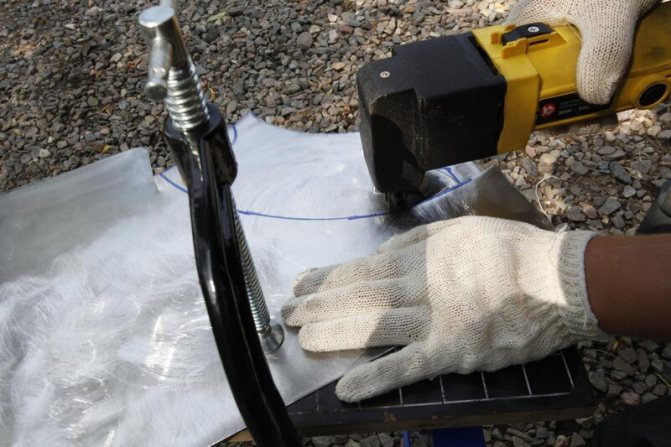
First you need to make a casing of insulation. Take a sheet of galvanized sheet or thin aluminum for this. Cut two rectangles out of it if you will be making a casing of two halves. Or one rectangle, but with the expectation that after manufacturing, Potapov's vortex heat generator, which was assembled by hand, will completely fit in it.
It is best to bend the sheet on a large diameter pipe or use a cross member. Place the cut sheet on it and press the wooden block on top with your hand. With the other hand, press on the sheet of tin so that a small bend is formed along the entire length. Move the workpiece slightly and repeat the operation again. Do this until you have a cylinder.
- Connect it with the lock used by the downpipe tinsmiths.
- Make covers for the casing with holes for connecting the generator.
- Wrap insulating material around the device. Fix the insulation with wire or thin strips of sheet metal.
- Place the device in the casing, close the covers.
There is another way to increase heat production: for this you need to figure out how the Potapov vortex generator works, the efficiency of which can approach 100% and higher (there is no consensus why this happens).
During the passage of water through the nozzle or jet, a powerful stream is created at the outlet, which hits the opposite end of the device. It twists, and heating occurs due to the friction of the molecules. This means that by placing an additional obstacle inside this flow, it is possible to increase the mixing of the liquid in the device.
Once you know how it works, you can start designing additional enhancements. This will be a vortex damper made of longitudinal plates located inside two rings in the form of an aircraft bomb stabilizer.
Stationary heat generator diagram.
Tools: welding machine, angle grinder.
Materials: sheet metal or flat iron, thick-walled pipe.
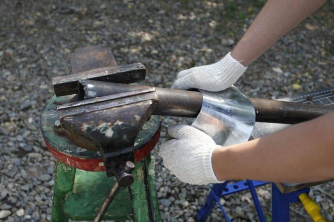
Make from a pipe of a smaller diameter than Potapov's vortex heat generator, two rings 4-5 cm wide. Cut identical strips from strip metal. Their length should be equal to a quarter of the length of the body of the heat generator itself. Choose the width so that after assembly there is a free hole inside.
- Secure the plate in a vise. Hang it on one side and the other of the ring. Weld the plate to them.
- Remove the workpiece from the clamp and flip it 180 degrees. Place the plate inside the rings and secure in the clamp so that the plates are opposite each other. Fix 6 plates in this way at an equal distance.
- Assemble the vortex heat generator by inserting the described device opposite the nozzle.
Probably, this product can be further improved. For example, instead of parallel plates, use steel wire by winding it into an air ball. Or make holes of different diameters on the plates. Nothing is said about this improvement, but this does not mean that it should not be done.
Diagram of a heat gun device.
- Be sure to protect Potapov's vortex heat generator by painting all surfaces.
- Its internal parts during operation will be in a very aggressive environment caused by cavitation processes. Therefore, try to make the body and everything in it from thick material. Don't skimp on hardware.
- Make several different caps with different inlets. Then it will be easier to select their diameter in order to obtain high performance.
- The same applies to the vibration damper. It can also be modified.
Build a small laboratory bench where you will run in all the characteristics. To do this, do not connect consumers, but loop the pipeline to the generator. This will simplify its testing and selection of the required parameters. Since it is hardly possible to find sophisticated devices for determining the coefficient of efficiency at home, the following test is proposed.
Turn on the vortex heat generator and note the time when it warms up the water to a certain temperature. It is better to have an electronic thermometer, it is more accurate. Then modify the design and run the experiment again, observing the rise in temperature. The more the water heats up at the same time, the more preference will have to be given to the final version of the established improvement in the design.
Have you noticed that the price of heating and hot water supply has increased and do not know what to do about it? The solution to the problem of expensive energy resources is a vortex heat generator. I will talk about how a vortex heat generator is arranged and what is the principle of its operation. You will also find out if it is possible to assemble such a device with your own hands and how to do it in a home workshop.


DIY CTG
The simplest option for implementation at home is a tubular-type cavitation generator with one or more nozzles for heating water. Therefore, we will analyze an example of making just such a device, for this you will need:
- Pump - for heating, be sure to choose a heat pump that is not afraid of constant exposure to high temperatures. It must provide a working pressure at the outlet of 4 - 12 atm.
- 2 pressure gauges and sleeves for their installation - located on both sides of the nozzle to measure the pressure at the inlet and outlet of the cavitation element.
- Thermometer for measuring the amount of heating of the coolant in the system.
- Valve for removing excess air from the cavitation heat generator. Installed at the highest point of the system.
- Nozzle - must have a bore diameter from 9 to 16 mm, it is not recommended to do less, since cavitation can occur already in the pump, which will significantly reduce its service life. The shape of the nozzle can be cylindrical, conical or oval, from a practical point of view, any will suit you.
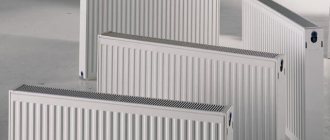
- Pipes and connecting elements (heating radiators in their absence) are selected in accordance with the task at hand, but the simplest option is plastic pipes for soldering.
- Automation of turning on / off the cavitation heat generator - as a rule, it is tied to the temperature regime, set to turn off at about 80 ° C and to turn on when it drops below 60 ° C. But you can choose the operating mode of the cavitation heat generator yourself.
Fig. 6: diagram of a cavitation heat generator
Before connecting all the elements, it is advisable to draw a diagram of their location on paper, walls or on the floor. Locations must be located away from flammable elements or the latter must be removed at a safe distance from the heating system.
Collect all the elements, as you depicted in the diagram, and check the tightness without turning on the generator. Then test the cavitation heat generator in the operating mode, a normal rise in the temperature of the liquid is 3 - 5 ° C in one minute.
Have you noticed that the price of heating and hot water supply has increased and do not know what to do about it? The solution to the problem of expensive energy resources is a vortex heat generator. I will talk about how a vortex heat generator is arranged and what is the principle of its operation. You will also find out if it is possible to assemble such a device with your own hands and how to do it in a home workshop.
A bit of history
A vortex heat generator is considered a promising and innovative development. Meanwhile, the technology is not new, since almost 100 years ago scientists were thinking about how to apply the phenomenon of cavitation.
The first experimental setup in operation, the so-called "vortex tube", was manufactured and patented by the French engineer Joseph Rank in 1934.
Rank was the first to notice that the air temperature at the entrance to the cyclone (air cleaner) differs from the temperature of the same air stream at the exit.However, at the initial stages of bench tests, the vortex tube was tested not for the heating efficiency, but, on the contrary, for the cooling efficiency of the air jet.
The technology underwent a new development in the 60s of the twentieth century, when Soviet scientists figured out how to improve the Rank pipe by launching a liquid into it instead of an air jet.
Due to the higher, in comparison with air, density of the liquid medium, the temperature of the liquid, when passing through the vortex tube, changed more intensively. As a result, it was experimentally found that the liquid medium, passing through the improved Ranque tube, heated up abnormally quickly with an energy conversion factor of 100%!
Unfortunately, there was no need for cheap sources of thermal energy at that time, and the technology did not find practical application. The first operating cavitation installations designed for heating a liquid medium appeared only in the mid-90s of the twentieth century.
A series of energy crises and, as a consequence, the increasing interest in alternative energy sources have led to the resumption of work on efficient converters of the energy of the movement of a water jet into heat. As a result, today it is possible to buy an installation of the required power and use it in most heating systems.
Advantages and disadvantages
In comparison with other heat generators, cavitation units differ in a number of advantages and disadvantages.
The advantages of such devices include:
- Much more efficient mechanism for obtaining thermal energy;
- Consumes significantly less resources than fuel generators;
- It can be used for heating both low-power and large consumers;
- Completely environmentally friendly - does not emit harmful substances into the environment during operation.
The disadvantages of cavitation heat generators include:
- Relatively large dimensions - electric and fuel models are much smaller, which is important when installed in an already operated room;
- High noise due to the operation of the water pump and the cavitation element itself, which makes it difficult to install it in household premises;
- Ineffective ratio of power and performance for rooms with a small square area (up to 60m 2 it is more profitable to use a unit running on gas, liquid fuel or equivalent electric power with a heating element). \
Operating principle
Cavitation allows not to give heat to water, but to extract heat from moving water, while heating it to significant temperatures.
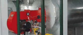
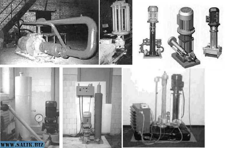
The device of working samples of vortex heat generators is outwardly uncomplicated. We can see a massive engine, to which a cylindrical "snail" device is connected.
The Snail is a modified version of the Rank's pipe. Due to its characteristic shape, the intensity of cavitation processes in the cavity of the "snail" is much higher in comparison with the vortex tube.
In the cavity of the "snail" there is a disk activator - a disk with a special perforation. When the disk rotates, the liquid medium in the "snail" is set in motion, due to which cavitation processes occur:
- The electric motor turns the disk activator
... The disc activator is the most important element in the design of the heat generator, and it is connected to the electric motor by means of a straight shaft or by means of a belt drive. When the device is turned on in operating mode, the motor transmits torque to the activator; - The activator spins up the liquid medium
... The activator is designed in such a way that the liquid medium, getting into the disk cavity, swirls and acquires kinetic energy; - Conversion of mechanical energy into heat
... Leaving the activator, the liquid medium loses its acceleration and, as a result of sharp braking, the effect of cavitation occurs. As a result, kinetic energy heats the liquid medium up to + 95 ° С, and mechanical energy becomes thermal.
Device and principle of operation
The principle of operation of the cavitation heat generator is the heating effect due to the conversion of mechanical energy into heat. Now let's take a closer look at the cavitation phenomenon itself. When excessive pressure is created in the liquid, vortices arise, due to the fact that the pressure of the liquid is greater than that of the gas contained in it, the gas molecules are released into separate inclusions - the collapse of bubbles. Due to the pressure difference, the water tends to compress the gas bubble, which accumulates a large amount of energy on its surface, and the temperature inside reaches about 1000 - 1200 ° C.
When the cavitation cavities pass into the zone of normal pressure, the bubbles are destroyed, and the energy from their destruction is released into the surrounding space. Due to this, thermal energy is released, and the liquid is heated from the vortex flow. The operation of heat generators is based on this principle, then consider the principle of operation of the simplest version of a cavitation heater.
The simplest model
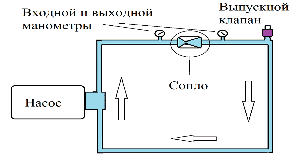
Fig. 1: Functional principle of the cavitation heat generator
Look at figure 1, here the device of the simplest cavitation heat generator is presented, which consists in pumping water by a pump to the place of the pipeline narrowing. When the water flow reaches the nozzle, the pressure of the liquid increases significantly and the formation of cavitation bubbles begins. When leaving the nozzle, the bubbles release thermal power, and the pressure after passing through the nozzle is significantly reduced. In practice, multiple nozzles or tubes can be installed to increase efficiency.
Potapov's ideal heat generator
The Potapov heat generator, which has a rotating disk (1) installed opposite the stationary one (6), is considered an ideal installation option. Cold water is supplied from the pipe located at the bottom (4) of the cavitation chamber (3), and the outlet is already heated from the upper point (5) of the same chamber. An example of such a device is shown in Figure 2 below:
Fig. 2: Potapov's cavitation heat generator
But the device did not receive wide distribution due to the lack of a practical justification for its operation.
Scope of application
| Illustration | Description of the scope |
| Heating ... Equipment that converts the mechanical energy of water movement into heat is successfully used to heat various buildings, from small private buildings to large industrial facilities. By the way, on the territory of Russia today one can count at least ten settlements where centralized heating is provided not by traditional boiler houses, but by gravitational generators. | |
| Heating running water for domestic use ... The heat generator, when connected to the network, heats the water very quickly. Therefore, such equipment can be used to heat water in an autonomous water supply system, in swimming pools, saunas, laundries, etc. | |
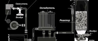
| Mixing immiscible liquids ... In laboratory conditions, cavitation units can be used for high-quality mixing of liquid media with different densities, until a homogeneous consistency is obtained. |
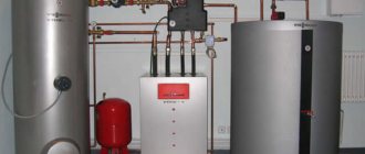
Integration into the heating system of a private house
In order to use a heat generator in a heating system, it must be introduced into it. How to do it correctly? In fact, there is nothing difficult about it.
A centrifugal pump (1 in the figure) is installed in front of the generator (marked with number 2 in the figure), which will supply water with a pressure of up to 6 atmospheres. An expansion tank (6 in the figure) and shut-off valves are installed after the generator.
Advantages of using cavitation heat generators
| Advantages of a vortex alternative energy source | |
| Profitability ... Due to the efficient consumption of electricity and high efficiency, the heat generator is more economical in comparison with other types of heating equipment. | |
| Small dimensions in comparison with conventional heating equipment of similar power ... A stationary generator suitable for heating a small house is twice as compact as a modern gas boiler. If you install a heat generator in a conventional boiler room instead of a solid fuel boiler, there will be a lot of free space. | |
| Low weight of the installation ... Due to their low weight, even large high-power plants can be easily placed on the floor of the boiler room without building a special foundation. There are no problems at all with the location of compact modifications.
| |
| Simple construction ... A heat generator of a cavitation type is so simple that there is nothing to break in it. The device has a small number of mechanically moving elements, and complex electronics are absent in principle. Therefore, the probability of a device breakdown, in comparison with gas or even solid fuel boilers, is minimal. | |
| No need for additional modifications ... The heat generator can be integrated into an existing heating system. That is, there is no need to change the diameter of the pipes or their location. | |
| No need for water treatment ... If a flowing water filter is needed for the normal operation of a gas boiler, then installing a cavitation heater, you can not be afraid of blockages. Due to specific processes in the working chamber of the generator, blockages and scale do not appear on the walls. | |
| Equipment operation does not require constant monitoring ... If you need to look after solid fuel boilers, then the cavitation heater works in autonomous mode. The operating instructions for the device are simple - just plug the engine into the network and, if necessary, turn it off. | |
| Environmental friendliness ... Cavitation plants do not affect the ecosystem in any way, because the only energy-consuming component is the electric motor. | |
Schemes for the manufacture of a heat generator of a cavitation type
In order to make a working device with our own hands, consider the drawings and diagrams of existing devices, the effectiveness of which has been established and documented in patent offices.
| Illustrations | General description of the designs of cavitation heat generators |
| General view of the unit ... Figure 1 shows the most common diagram of the device for a cavitation heat generator. The number 1 denotes the vortex nozzle on which the swirl chamber is mounted. On the side of the swirl chamber, you can see the inlet pipe (3), which is connected to the centrifugal pump (4). The number 6 in the diagram denotes the inlet pipes for creating a counter-disturbing flow. A particularly important element in the diagram is a resonator (7) made in the form of a hollow chamber, the volume of which is changed by means of a piston (9). The number 12 and 11 denote throttles that control the flow rate of water flows. | |
| Device with two series resonators ... Figure 2 shows a heat generator in which resonators (15 and 16) are installed in series. One of the resonators (15) is made in the form of a hollow chamber surrounding the nozzle, indicated by number 5. The second resonator (16) is also made in the form of a hollow chamber and is located at the opposite end of the device in the immediate vicinity of the inlet pipes (10) supplying disturbing flows. The chokes marked with numbers 17 and 18 are responsible for the rate of supply of the liquid medium and for the mode of operation of the entire device. |
| Heat generator with counter resonators ... In fig.3 shows a rare, but very effective scheme of the device, in which two resonators (19, 20) are located opposite each other. In this scheme, the vortex nozzle (1) with the nozzle (5) bends around the outlet of the resonator (21). Opposite to the resonator marked with 19, you can see the inlet (22) of the resonator at number 20. Note that the exit holes of the two resonators are aligned. |

| Illustrations | Description of the swirl chamber (snails) in the design of the cavitation heat generator |
| "Snail" of the cavitation heat generator in cross section ... In this diagram, you can see the following details: 1 - the body, which is made hollow, and in which all the fundamentally important elements are located; 2 - shaft on which the rotor disk is fixed; 3 - rotor ring; 4 - stator; 5 - technological holes made in the stator; 6 - emitters in the form of rods. The main difficulties in the manufacture of the listed elements can arise in the manufacture of a hollow body, since it is best to make it cast. Since there is no equipment for casting metal in the home workshop, such a structure, albeit at the expense of strength, will have to be welded. |
| Scheme of alignment of the rotor ring (3) and the stator (4) ... The diagram shows the rotor ring and the stator at the moment of alignment when the rotor disk rotates. That is, with each combination of these elements, we see the formation of an effect similar to the action of the Rank pipe.
| |
| Rotary displacement of rotor ring and stator ... This diagram shows the position of the structural elements of the "snail" at which a hydraulic shock (collapse of bubbles) occurs, and the liquid medium is heated. That is, due to the speed of rotation of the rotor disk, it is possible to set the parameters of the intensity of the occurrence of hydraulic shocks that provoke the release of energy. Simply put, the faster the disc spins up, the higher the outlet water temperature will be. |

Price overview
Of course, a cavitation heat generator is practically an abnormal device, it is an almost ideal generator, it is difficult to buy it, the price is too high. We propose to consider how much a cavitation heating device costs in different cities of Russia and Ukraine:
Cavitation vortex heat generators have simpler drawings, but they are somewhat inferior in efficiency. At the moment there are several market leaders: a rotary hydro-shock pump-heat generator "Radex", NPP "New Technologies", an electric shock "Tornado" and an electro-hydraulic shock "Vektorplus", a mini-device for a private house (LATR) TSGC2-3k ( 3 kVA) and the Belarusian Yurle-K.
Photo - Tornado heat generator
The sale is carried out in dealerships and partner stores in Russia, Kyrgyzstan, Belarus and other CIS countries.
To provide economical heating of a residential, utility or industrial premises, the owners use various schemes and methods for obtaining thermal energy. In order to assemble a heat generator of cavitation action with your own hands, you need to understand the processes that allow you to generate heat.
Let's summarize
Now you know what a popular and demanded source of alternative energy is. This means that it will be easy for you to decide whether such equipment is suitable or not. I also recommend watching the video in this article.
Every year, the rise in heating prices makes us look for cheaper ways to heat living space in the cold season. This is especially true for those houses and apartments that have a large square. One of these ways of saving is vortex. It has many advantages, as well allows you to save
on creation.The simplicity of the design will not make it difficult to collect, even from beginners. Next, we will consider the advantages of this heating method, and also try to draw up a plan for assembling a heat generator with our own hands.

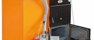
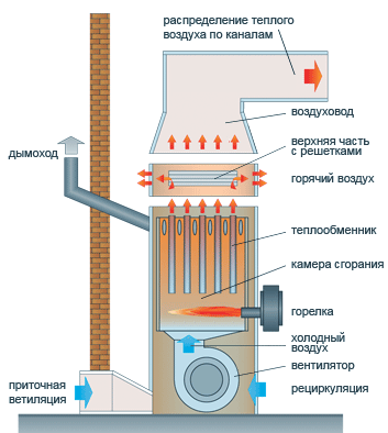
A heat generator is a special device, the main purpose of which is to generate heat by burning the fuel loaded into it. In this case, heat is generated, which is spent on heating the coolant, which in turn directly performs the function of heating the living space.
The first heat generators appeared on the market back in 1856, thanks to the invention of the British physicist Robert Bunsen, who, in the course of a series of experiments, noticed that the heat generated during combustion can be directed in any direction.
Since then, generators, of course, have been modified and are capable of heating much more area than they were 250 years ago.
The principal criterion by which generators differ from each other is the fuel to be charged. Depending on this, they distinguish the following types
:
- Diesel heat generators - generate heat from the combustion of diesel fuel. They are capable of heating large areas well, but it is better not to use them for the house due to the production of toxic substances formed as a result of fuel combustion.
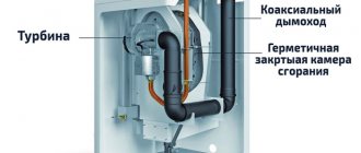
- Gas heat generators - work on the principle of continuous gas supply, burning in a special chamber that also generates heat. It is considered a very economical option, but the installation requires special permission and increased safety.
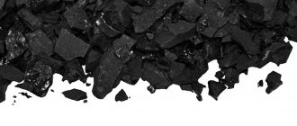
- Solid fuel generators are similar in design to a conventional coal stove, with a combustion chamber, a soot and ash compartment, and a heating element. They are convenient for operation in open areas, since their operation does not depend on weather conditions.
- - their principle of operation is based on the process of thermal conversion, in which bubbles formed in the liquid provoke a mixed flow of phases, which increases the amount of heat generated.
Making a heat generator with your own hands is a rather complicated and painstaking process. As a rule, this device is necessary to provide economical heating in homes. Heat generators come in 2 designs: static and rotary. In the first case, a nozzle must be used as the main element. In a rotary generator, an electric motor should be used to create cavitation.
This unit is a modernized centrifugal pump, or rather its housing, which will serve as a stator. You cannot do without a working chamber and branch pipes.
Inside the body of our hydrodynamic design is a flywheel as an impeller. There is a huge variety of rotary designs for heat generators. The simplest of these is the disc design.
The required number of holes is applied to the cylindrical surface of the rotor disc, which must have a certain diameter and depth. It is customary to call them "Griggs cells". It should be noted that the size and number of drilled holes will vary depending on the caliber of the rotor disc and the speed of the motor shaft.
The body of such a heat source is most often made in the form of a hollow cylinder. In fact, it is a regular pipe with welded flanges at the ends. The gap between the inside of the housing and the flywheel will be very small (approximately 1.5-2 mm).
Direct heating of water will occur precisely in this gap. Heating of the liquid is obtained due to its friction against the surface of the rotor and the housing at the same time, while the flywheel disk moves at almost maximum speeds.
Cavitation (bubble formation) processes that occur in rotor cells have a great influence on the heating of the liquid.
A rotary heat generator is a modernized centrifugal pump, more precisely, its housing, which will serve as a stator
As a rule, the disc diameter in this type of heat generators is 300 mm, and the rotation speed of the hydraulic device is 3200 rpm. The speed will vary depending on the size of the rotor.
Analyzing the design of this installation, we can conclude that its operating life is rather small. Due to the constant heating and abrasive action of the water, the gap gradually widens.
It should be noted that rotary heat generators create a lot of noise during operation. However, in comparison with other hydraulic devices (static type), they are 30% more efficient.
Views
The main task of a cavitation heat generator is the formation of gas inclusions, and the quality of heating will depend on their quantity and intensity. In modern industry, there are several types of such heat generators, which differ in the principle of generating bubbles in a liquid. The most common are three types:
- Rotary heat generators
- the working element rotates due to the electric drive and generates fluid swirls; - Tubular
- change the pressure due to the system of pipes through which the water moves; - Ultrasonic
- the inhomogeneity of the liquid in such heat generators is created due to sound vibrations of low frequency.
In addition to the above types, there is laser cavitation, but this method has not yet found industrial implementation. Now let's consider each of the types in more detail.
Rotary heat generator
It consists of an electric motor, the shaft of which is connected to a rotary mechanism designed to create turbulence in the liquid. A feature of the rotor design is a sealed stator, in which heating takes place. The stator itself has a cylindrical cavity inside - a vortex chamber in which the rotor rotates. The rotor of a cavitation heat generator is a cylinder with a set of grooves on the surface; when the cylinder rotates inside the stator, these grooves create inhomogeneity in the water and cause cavitation processes.
Fig. 3: design of the rotary type generator
The number of recesses and their geometrical parameters are determined depending on the model. For optimal heating parameters, the distance between the rotor and the stator is about 1.5 mm. This design is not the only one of its kind; for a long history of modernizations and improvements, the rotary-type working element has undergone a lot of transformations.
One of the first effective models of cavitation transducers was the Griggs generator, which used a disc rotor with blind holes on the surface. One of the modern analogues of disk cavitation heat generators is shown in Figure 4 below:
Fig. 4: disc heat generator
Despite the simplicity of the design, rotary-type units are quite difficult to use, since they require accurate calibration, reliable seals and compliance with geometric parameters during operation, which makes them difficult to operate. Such cavitation heat generators are characterized by a rather low service life - 2 - 4 years due to cavitation erosion of the body and parts. In addition, they create a fairly large noise load during the operation of the rotating element. The advantages of this model include high productivity - 25% higher than that of classic heaters.
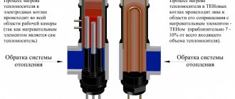
Tubular
The static heat generator has no rotating elements. The heating process in them occurs due to the movement of water through pipes tapering along the length or due to the installation of Laval nozzles.The supply of water to the working body is carried out by a hydrodynamic pump, which creates a mechanical force of the liquid in a narrowing space, and when it passes into a wider cavity, cavitation vortices arise.
Unlike the previous model, tubular heating equipment does not make much noise and does not wear out so quickly. During installation and operation, there is no need to worry about accurate balancing, and if the heating elements are destroyed, their replacement and repair will be much cheaper than with rotary models. The disadvantages of tubular heat generators include significantly lower performance and bulky dimensions.
Ultrasonic
This type of device has a resonator chamber tuned to a specific frequency of sound vibrations. A quartz plate is installed at its input, which vibrates when electrical signals are applied. The vibration of the plate creates a ripple effect inside the liquid, which reaches the walls of the resonator chamber and is reflected. During the return motion, the waves meet with forward vibrations and create hydrodynamic cavitation.
Fig. 5: working principle of the ultrasonic heat generator
Further, the bubbles are carried away by the water flow along the narrow inlet pipes of the thermal installation. When passing into a wide area, the bubbles collapse, releasing thermal energy. Ultrasonic cavitation generators also have good performance as they do not have rotating elements.
Manufacturing of vortex heat generator Potapov
Many other devices have been developed that operate on completely different principles. For example, Potapov's vortex heat generators, made by hand. They are called static conventionally. This is due to the fact that the hydraulic device has no rotating parts in the structure. As a rule, vortex heat generators receive heat using a pump and an electric motor.
The most important step in the process of making such a heat source with your own hands will be the choice of the engine. It should be selected depending on the voltage. There are numerous drawings and diagrams of a do-it-yourself vortex heat generator, which demonstrate methods for connecting an electric motor with a voltage of 380 volts to a 220-volt network.
Frame assembly and engine installation
Do-it-yourself installation of a Potapov heat source begins with the installation of an electric motor. Attach it to the bed first. Then use an angle grinder to make the corners. Cut them from a suitable square. After making 2-3 squares, fasten them to the crossbar. Then use a welding machine to assemble a rectangular structure.
If you do not have a welding machine at hand, you do not need to cut the squares. Just cut out the triangles in the places of the intended fold. Then bend the squares using a vise. Use bolts, rivets and nuts to secure.
After assembly, you can paint the frame and drill holes in the frame to mount the engine.
Installing the pump
The next important element of our vortex hydroconstruction will be the pump. Nowadays, in specialized stores, you can easily purchase a unit of any power. When choosing it, pay close attention to 2 things:
- It must be centrifugal.
- Choose a unit that will work optimally with your electric motor.
After you have purchased the pump, attach it to the frame. If there are not enough crossbars, make 2-3 more corners. In addition, it will be necessary to find a coupling. It can be turned on a lathe or purchased from any hardware store.
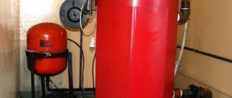
Vortex cavitation heat generator Potapov on wood, made by hand, consists of a body, which is made in the form of a cylinder.It is worth noting that through holes and nozzles must be present at its ends, otherwise you will not be able to correctly attach the hydro structure to the heating system.
Insert the jet just behind the inlet. He is selected individually. However, remember that its hole should be 8-10 times smaller than the pipe diameter. If the hole is too small, the pump will overheat and will not be able to circulate the water properly.
In addition, due to vaporization, Potapov's vortex cavitation heat generator on wood will be highly susceptible to hydroabrasive wear.
How to make a pipe
The process of making this element of Potapov's heat source on wood will take place in several stages:
- First, use a grinder to cut a piece of pipe with a diameter of 100 mm. The length of the workpiece must be at least 600-650 mm.
- Then make an external groove in the workpiece and cut the thread.
- Then make two rings 60 mm long. the caliber of the rings must correspond to the diameter of the pipe.
- Then cut the threads for the half rings.
- The next stage is the manufacture of lids. They must be welded from the side of the rings where there is no thread.
- Next, drill a central hole in the covers.
- Then use a large drill bit to chamfer the inside of the cover.
After the operations done, the wood-fired cavitation heat generator should be connected to the system. Insert a branch pipe with a nozzle into the pump hole where the water is supplied from. Connect the other fitting to the heating system. Connect the outlet from the hydraulic system to the pump.
If you want to regulate the temperature of the liquid, install a ball mechanism right behind the nozzle.
With its help, the Potapov heat generator on wood will run water throughout the device much longer.
Is it possible to increase the performance of the Potapov heat source
In this device, as in any hydraulic system, heat loss occurs. Therefore, it is desirable to surround the pump with a water jacket. To do this, make a heat-insulating housing. Make the outer gauge of such a protective device larger than the diameter of your pump.
A ready-made 120 mm pipe can be used as a blank for thermal insulation. If you do not have such an opportunity, you can make a parallelepiped with your own hands using sheet steel. The size of the figure should be such that the entire structure of the generator can easily fit into it.
The workpiece must be made only of quality materials in order to withstand the high pressure in the system without problems.
In order to further reduce heat loss around the case, make thermal insulation, which can later be sheathed with a sheet metal casing.
Any material that can withstand the boiling point of water can be used as an insulator.
The manufacture of a heat insulator will take place in several stages:
- First, assemble the device, which will consist of a pump, a connecting pipe, a heat generator.
- After that, select the optimal dimensions of the thermal insulation device and find a pipe of a suitable caliber.
- Then make the covers on both sides.
- After that, securely fasten the internal mechanisms of the hydraulic system.
- At the end, make an inlet and fix (weld or screw) a pipe into it.
After the operations done, weld the flange on the end of the hydraulic pipe. If you have difficulties with mounting internal mechanisms, you can make a frame.
Be sure to check the tightness of the heat generator assemblies and your hydraulic system for leaks. Finally, remember to adjust the temperature with a ball.
Frost protection
First of all, make an insulation casing. To do this, take a galvanized sheet or a thin sheet of aluminum. Cut out two rectangles. Remember that it is necessary to bend the sheet on a mandrel with a larger diameter.You can also bend the material on the crossbar.
First, lay the sheet you cut out and press down on top of it with a piece of wood. With the other hand, press on the sheet so that a slight bend forms along the entire length. Then move your workpiece a little to the side and continue bending it until you get a hollow cylinder.
Then make a cover for the casing. It is advisable to wrap the entire thermal insulation structure with a special heat-resistant material (glass wool, etc.), which must be subsequently secured with a wire.