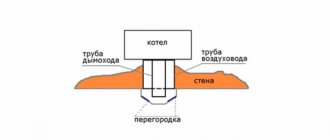
Principle of operation

The principle of operation of the burners is to pre-mix the fuel with air, ensure the supply of this mixture for combustion and make sure that the combustion products go through the combustion process completely.
The work of this device is divided into three stages:
- Training... At this stage, the preparation of individual elements of the future combustible mixture is carried out. At the time of the preparatory stage, the air and fuel are given the necessary characteristics: direction, temperature, speed.
- Mixing... Air and the required amount of fuel are mixed, resulting in a mixture of a combustible nature.
- Combustion... At the final stage of the burner operation, the combustion process occurs, or rather, the oxidation reaction of the elements of the combustible action with the help of oxygen takes place. Ultimately, the mixture ignites thanks to a nozzle that is placed at the end point of the tube.
Attention, even taking into account the simple design of the burners in the event of malfunctions, in no case should you try to eliminate them yourself.
In gas burners, there are also additions that ensure the safety and automation of the device.
These include:
- Automation, independently turns off devices as a result of troubleshooting.
- Ignition, carried out thanks to a special pieza element or electricity.
1. According to the method of mixing gas with air, burners are divided into three groups:
Burners without preliminary mixing of gas with air, gas and air are supplied to the furnace (combustion zone) separately - diffusion burners.
· Gas burners in which there is a partial mixing of gas with air. In these burners, gas and air are mixed both in the burner and in the working space of the furnace, this happens simultaneously with the combustion process - low pressure injection burners.
· Full mixing burners, inside of which gas and air are mixed, i.e. preliminary processing of the gas-air mixture before it leaves the burner into the combustion zone - injection burners of medium pressure and mixing.
2. By device:
· Diffusion;
· Injection;
· Mixing;
· Combined.
3. By pressure:
· Low pressure (gas up to 500 mm of water column, air up to 100 mm of water column);
Medium pressure (gas 500-15000 mm w.st., air 100-300 mm w.st.)
4. Depending on the outflow of the gas-air mixture:
· Single-flare - in which the mixture comes out through one hole;
· Multi-flare - the mixture comes out through a large number of holes.
Diffusion burners
In diffusion burners (atmospheric), gas and air enter the furnace separately and mixture formation occurs due to diffusion (slow penetration of one substance into another) when they touch. They represent a pipe segment with a diameter of 50-70 mm plugged at the end, near which two rows of holes are drilled in a checkerboard pattern with a diameter of 0.5-3 mm, with a distance (step) of 4-16 hole diameter. The rows of holes are located at an angle of 60-120 °. The number of holes depends on the line capacity.
Air enters the furnace from the surrounding space due to the vacuum created by the chimney and the injecting action of the gas jet. The gas enters the burner under pressure, exits through the burner holes into the furnace, mixes with the ambient air and burns out in the form of separate small torches.At a low thermal load, the gas streams suck in air from all sides and, mixing with it, quickly burn out with a blue-blue glowing flame. Such a burner can operate at a gas pressure of 30-120 mm Hg. from TO(excess air ratio) 1.2-1.6.
The capacity of the burners is 1-10 m3 / h, there is up to 100 m3 / h, but this is not profitable. The burners can also operate at an average gas pressure of up to 3000 mm.w.
Diffusion burners are simple in design, have small dimensions, are easy to maintain, have a stable flame under variable loads, are easy to regulate by changing the gas supply, and exclude flame breakthrough.
Diffuse combustion - This is combustion in which there is no premixing of gas with air. This combustion is fairly stable under the following conditions:
1. If the flow rate of the gas jet does not exceed the specified limit.
2. If there are no air streams capable of disrupting the combustion of the gas jet.
Disadvantage- large excess of air, the torch is long and requires a high furnace height.
It is necessary to constantly maintain a relatively high vacuum in the furnace; this requires careful lining of the entire boiler.
Injection burners
Burners in which the formation of a gas-air mixture occurs due to a gas jet (partial preliminary incomplete mixing). The main element of an injection burner is an injector that sucks in air from the surrounding space into the inside of the burner.
Depending on the amount of air supplied, the burners can be:
· Complete preliminary mixing of gas with air;
· Incomplete air injection.
In these burners, primary air is sucked in by the injection of gas exiting the nozzle. To improve injection, the burner has a converging part CONFUSER (throat) and an expanded cylindrical DIFFUSER. In the diffuser, the speed decreases and the pressure increases. From the diffuser, the gas-air mixture enters the burner head, and from there, through an opening of 3-6 mm, it enters the furnace in the form of small torches. The primary air supply is controlled by rotating the adjusting washer, i.e. the degree of opening of the air gap is regulated. Secondary air is supplied through the blower doors, which are also regulated by the opening degree.
During normal operation of the burners and complete combustion of the gas, bluish purple torch.
With a lack of primary air, the burning rate decreases, the flame is drawn out, the color of the flame becomes yellow-straw.
With an excessive increase in the primary air supply, a loud noise appears in the burner and flame separation is possible. The operator must skillfully regulate the supply of primary and secondary air based on the color of the flame.
Dignity self-regulating, no air supply devices required.
Disadvantage loud noise and instability at low loads.
The principle of operation of this burner is that the gas from the gas pipeline enters the burner nozzle with excess pressure. As it exits the nozzle, its speed increases and the pressure drops. The gas jet enters the injector at high speed, forming a vacuum around itself and thereby sucking in the primary air from the atmosphere.
Forced air burner
These burners have unlimited applications. Gas consumption from several m3 to 5000 and more. In these burners, the process of gas-air mixture formation begins in the burner itself and ends in the firebox. The gas is burned with a short, non-luminous flame.
The air required for combustion is supplied forcibly by a fan. The supply of gas and air is carried out through separate pipes, therefore the burners are called two-wire or mixing,because in them there is a complete mixing of the gas-air mixture. These burners operate at low to medium pressure.Gas with a pressure of up to 1200Pa enters the nozzle 1 and leaves it through 8 holes with a diameter of 4.5 mm. The holes are located at an angle of 30 ° to the axis of the burner, in the housing 2 of the burner, special blades are arranged, giving rotational movements to the air flow. Thus, the gas in the form of small streams intersects with the swirling air flow and a well-mixed gas-air mixture is created. The burner ends with a ceramic tunnel 4 with ignition holes.
Advantages: a wide range of automatic regulation, the possibility of burning a large amount of gas, air preheating, the burner operates with a minimum excess air ratio.
Disadvantage: the consumption of electrical energy for the operation of the fan.
Types and functions of burners

For space heating, not only stationary heating systems are used.
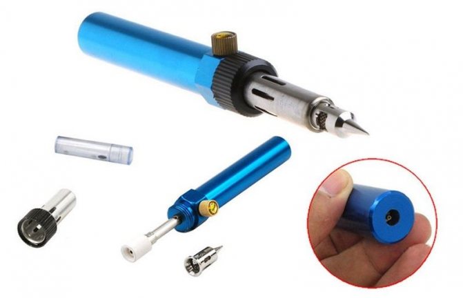
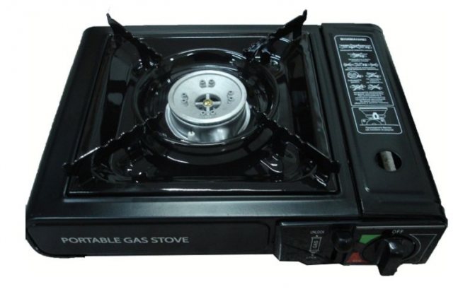
There are four portable devices that are more convenient to use in some circumstances:
- Plate
- Lamp
- Heater
- Burner
Natural gas heaters are classified as air heaters.
The design of these devices is simple:
- housing,
- gas stove,
- heat exchanger,
- element capable of heating,
- balloon.
Each type of heater always has an additional possibility of connecting to a gas pipeline.

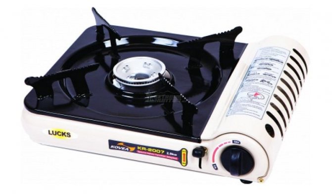
The stove works thanks to a fuel tank. With this device, cooking becomes comfortable regardless of location. This unit includes a robust housing. The body itself is made of high quality steel, which is further covered with a special enamel that protects against damage of various nature.
A lamp powered by gaseous fuel is a kind of element that emits light. The design of the lamp is similar to that of a burner.
The difference lies in the fact that its head is represented by a rod, on which a special catalytic mesh is put on, which is the direct source of the glow.
For protection, a glass shade is put on over the mesh.
There are burners complete with add-ons to improve the performance of the appliances.
First of all, it is worth considering the classification of burners depending on the type of fuel used:
Gas

This type is common - natural gas refers to the fuel available to the consumer.
Gas burner devices are divided into two types in accordance with the method of supplying the oxidizer to the working area: pressurized and injection.
Pressurized burners.
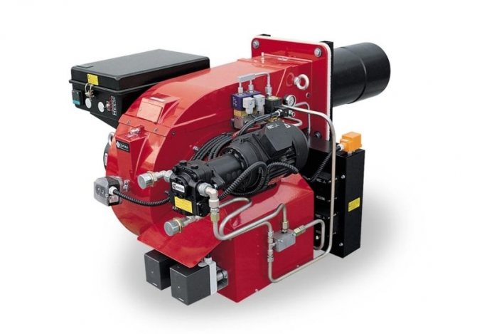
They run on gaseous fuel and differ significantly in design - a built-in fan, mechanical delivery of the oxidizer (air) to the working area is provided.
With the help of the fan, the power is regulated and, in accordance with this, the operation of the device is improved, which affects the efficiency.
Additional noise is considered a disadvantage, but this is eliminated by installing special noise reduction add-ons.
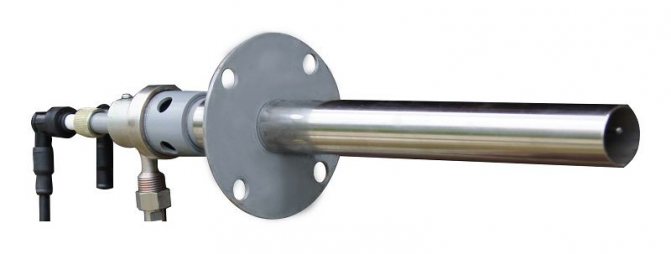
Injection burners also called atmospheric. Such a device is most often included in the additional standard equipment for boilers. The operation of the device consists in supplying air to the working area due to the "injection effect" - the required volume of oxidizer required for the full flow of the combustion process enters the flow of gaseous fuel using high pressure.
During manufacture, the device is set to standard settings aimed at working with natural gas.
In order for the heating system to run on liquefied gas, additional equipment will need to be installed.
The advantages of this type of burner devices are simplicity of design, absence of noise, complete safety, long service life.
Liquid fuel

For oil burners, petroleum products are used as fuel, which go through various stages of processing. Biofuel or waste oil is also used. Those burner devices that perform work using diesel fuel are popular.
Diesel burners are not inferior to gas burners in terms of the quality of work.
At the same time, maintenance does not require large costs, the power of their work is a constant value and, which is no less important, they are able to work in conditions of negative temperatures.
Burners operating on fuel oil are considered economical, since fuel oil has a low cost, reliable in terms of a long service life of the device without preventive maintenance.
Oil burners are not used in domestic premises. The main area of application is objects of industrial importance, boiler houses operating for centralized heating.
Multi-fuel or combined

For these devices, it is possible to use various types of fuel without the need to install additional equipment. The cost of the device is high, but the efficiency is much lower than in other burners. Maintenance is much more complicated and therefore expensive.
Burner classification according to power:
- Low-power - ≥1500 W, used for a short time;
- Average power - from 1500 to 2500 W;
- Powerful - ≤ 2500 W.
The burners are connected to cylinders filled with gaseous fuel.
There are several types of cylinder connections, each suitable for any type of burner:
- Threaded connection - the burner is screwed onto the thread or it is done using an additional hose that is connected to the burner device.
- To perform a collet connection, a special push-type mount is used. The balloon, which is connected in this way, has a thin shell.
- The disposable connection cannot be disconnected from the burner until the fuel is completely consumed. This is due to the fact that there is no valve in the mount, and in case of untimely opening
- The valve connection is reliable, since even the slightest fuel leaks are avoided.
Some burners are equipped with additional functions that simplify the use of this device.

Power regulator... It allows you to adjust the power of the burner device, it is located on a threaded union, which is screwed to the cylinder. Since the regulator is located at a considerable distance directly from the burner, it is not always possible to keep the power under control. To eliminate this problem, two regulators are installed - on the burner device and on the fitting.
Piezo ignition... This addition greatly simplifies the initial stage of work. The ignition switch is located so that the burner start button is located under it. Therefore, the operating principle of the entire system is simple.
In high humidity, the device may malfunction.
Preheating... The operation of the system lies in the fact that the part of the pipe through which the fuel enters the combustion site is located not far from the burner head, therefore, in working condition, it is enveloped in a flame.
What kind of burners are there?
Burner types differ according to the type of fuel used.
Gas-burners use gaseous fuels, they are convenient and are often used in heating boilers. Due to their simplicity of design, they are reliable and fail-safe. Built-in burner automation ensures safety and comfortable operation of the burners. You can buy a gas burner for a furnace and a boiler from us.
If you want to buy a liquid fuel burner, pay attention to diesel, fuel oil, oil burners and waste oil burners... In such burners, liquid fuel is atomized under pressure, fuel vapors form a combustible mixture with air and ignite.
- Diesel burners are cheaper than gas burners, safer to use and easier to operate. Unlike gas burners, they do not require a special permit for installation. But diesel fuel is more expensive than gas fuel - accordingly, the operation of such a burner will cost more.
- Heavy oil burners use fuel oil M40 and M100, which is cheaper than diesel fuel, which makes the operation of heavy oil burners more economical
- Fired burners are beneficial in that they can help reduce heating costs and dispose of waste oils without harming the environment.
A combination burner is worth buying if you want to use more than one type of fuel, but several. Such burners can automatically switch from the main type of fuel to the reserve one. Combined burners ensure the stable operation of boiler equipment, since in case of problems with the supply of one type of fuel, they can easily switch to another. They are used where gasification is only expected, or where even short-term interruptions in heating are unacceptable. On our website you can purchase oil-gas burners, gas / diesel dual fuel burners and other multi-fuel burners.
Pellet burners operate on wood pellets and are economical and environmentally friendly equipment. It is especially advantageous to use a pellet burner for those who have a large amount of wood waste - this will allow them to be disposed of and reduce heating costs. Check out the prices for pellet burners right now in the online store "Energomir"
An important characteristic when choosing a burner is the type of power regulation.
Single stage burners - operate at one preset power from the range possible for the given burner. Single-stage gas burners are used in boilers, furnaces and low-power units. The principle of operation is turning on and off the burner of a boiler or heat generator to maintain a given temperature level in the system.
Two stage burners - have 2 modes of operation - 100% and 50% of the total capacity. The transition from one operating mode to another is carried out by an automatic system. The indicated power levels can also be adjusted from the possible range for a given burner.
Sliding two stage burners - also have 2 modes of operation, but the transition from one mode to another is smooth. Most of these burners can be converted into modulating ones by installing a special automation unit.
Three stage burners - can operate in three power modes.
Modulating burners - allow you to smoothly change the power according to temperature or pressure in a heating boiler or steam boiler, heat generator, oven, drying drum, depending on the sensor used.
All types of burners presented can be ordered from us.
Burner advantages
Positive aspects of burners operating on gaseous fuels:
- Ease of use, since the design features of this type of burners are primitive and do not require additional experience;
- There is no need for preparation before starting to use;
- Achieving high capacities;
- Flame regulation;
- Cleanliness, and this is important, since there is no need to allocate additional time for cleaning accessories;
- There is no need for additional maintenance of the burner elements, because carbon deposits do not remain after fuel combustion;
- Low cost price.
Advantages of liquid fuel devices:
- This type of fuel is consumed much more economically than gas;
- Throughout the work, the power indicator remains unchanged;
- Works at low temperatures.
Classification of gas burners. What are the burners
Kinetic blast burners should be used in cases where it is required to achieve high thermal stresses in the furnace volume and combustion with minimal excess air in a non-luminous or low-luminous flame.
The disadvantages of kinetic burners are the possibility of flame breakthrough, their increased dimensions, and significant weight.
To carry out premixing, bulky injection blast burners or fan air supply have to be used. Premixing conditions do not allow working on air blast with temperatures above 500-600 ° C, since there is a danger of gas ignition in the burner body during mixing.
Kinetic burners, both injection and blower burners, have become very widespread when burning gas in various industrial furnaces and boilers.
Insufficient gas pressure, as well as the desire to reduce the size of the burner, especially for high capacities (over 100 m 3 / h), force the use of forced feed
air into the mixing chamber of the burner. Such burners are called blast, mixing or two-wire burners. An example is a turbulent burner with tangential air inlet and gas outlet through multiple small bore holes (Fig. VI-1). The speed of the tangential outlet of air into the mixer at this burner is assumed to be 15-25 m / s, the speed of the mixture outlet is 20-30 m / s, which prevents the flame from penetrating into the burner body.
Mixing blast burners with tangential air supply and axial or radial gas jets are widely used due to their ability to operate at low gas pressures and moderate air pressure (80-150 mm H2O). Their disadvantage is the rather large dimensions of the mixer. The torch of the burner is characterized by a short length and a large cone angle.
With an unsuccessful choice of the output speed and degree of twist, sometimes the flame is pulled to the central part of the wellhead and even within the burner mixer, which causes heating and disruption of its operation.
There are kinetic blast burners with air supply along the burner axis and multi-jet radial gas outlet. If it is possible to increase the size of the mixing chamber, to develop it in length, then good mixing is ensured even with a single-jet gas supply and relatively low air velocities, that is, at a reduced air pressure.
A similar mixer is also used for low-capacity front-type burners. The considered types of mixers are the most typical for fan-blown kinetic burners.
Often the mixing of gas with air is carried out in a diffuser with air supply through a central nozzle and gas supply through the annular space. Such burners are classified by us as injection burners, since in them the air jet sucks in flammable gas.
Kinetic burners can operate with minimum excess air ratios with near complete combustion. The calculated excess air ratio is usually taken as 1.05-1.10. The thermal stress of the volume in which the gas is combusted can amount to tens and even hundreds of thousands of kWp / m 3.
To choose the optimal gas boiler, you need to understand its features.
The most widespread in everyday life are hot water boilers of low power.
These units are economical and easy to operate, and come in many configurations and models, each with its own advantages.
One of the main elements of a gas boiler is its burner. This is a special equipment that prepares fuel for combustion and feeds it into the combustion chamber, where a stream of gas-air mixture ignites and releases heat.The correct choice of the burner will ensure maximum fuel combustion efficiency, increase the overall efficiency (efficiency) of the boiler and reduce the financial costs of fuel.
Classification of gas burners
There are various types of gas burners. To make the right choice of a burner, you need to take into account the type of combustion gas, its calorific value, pressure, purpose and design of the boiler.
By gas overpressure
Problems
Any type of burner device also has negative sides.
Disadvantages of gas powered devices:
- Under natural conditions, there is no way to replenish fuel reserves;
- Inability to transport gas cylinders on airplanes and trains by public transport;
- At a negative temperature, gaseous fuel tends to thicken, as a result of which the pressure indicator decreases and, ultimately, the burner device fails.
Negative qualities of the work of devices using liquid fuel:
- Parts of the burner structure are prone to deviations in operation, therefore, they must be serviced quite often;
- High price;
- Possibility of fuel leakage;
- The need for additional preparation before starting work;
- Decent weight and size.
How to choose a burner

The required power of the device depends primarily on the number of consumers. With a small number of consumers, a low-power burner is sufficient. If there are 5 or 6 users, the device with the highest power is required. In the event that the number of users is much more, it is worth stocking up on several devices.
The design of the selected model depends only on personal preferences: a minimum size burner is required, or the cooking speed is important, and the device will become much larger.
For convenience, it is worth purchasing a device with piezo ignition.
Type of cylinder attachment. It is equally important to think about additional equipment. First of all, there is a need for a case for transporting the device. Convenient when a special cookware holder is included with the burner.
The additions also include special protection against gusts of wind - blowing out the flame. Such a device significantly saves fuel. When choosing an add-on, pay attention to the design, since the presence of plastic parts in it is unacceptable.
Combined burners:
Classification of gas burners A gas burner is a device that supplies a certain amount of combustible gas and an oxidizer (air or oxygen), creates conditions for mixing them, and transports the resulting mixture to the place of combustion and combustion of gas. There are burners in which only gas or gas and air are supplied to the place of combustion, but without their preliminary mixing inside the burner. Requirements for burners: · creation of conditions for complete combustion of gas with a minimum excess of air and the release of harmful substances in combustion products; · Ensuring the necessary heat transfer and maximum use of the heat of the gas fuel; · The presence of regulation limits, not less than the required change in the thermal power of the unit; · Absence of strong noise, the level of which should not exceed 85 dB; · Simplicity of design, ease of repair and safety of operation; · The possibility of using automatic regulation and safety; · Compliance with modern requirements of industrial aesthetics. The main functions of gas burners are: gas and air supply to the gas combustion front, mixture formation, stabilization of the ignition front, ensuring the required intensity of the gas combustion process.By the method of gas combustion, all burners can be divided into three groups: · without preliminary mixing of gas with air - diffusion; · With incomplete preliminary mixing of gas with air - diffusion-kinetic; · With complete premixing of gas with air - kinetic. In addition, burners can be classified according to the air supply method, the location of the burner in the combustion chamber, the emissivity of the burner, and the gas pressure. The classification of burners according to the method of air supply is widespread. On this basis, burners are subdivided as follows: · blow-free, in which air enters the furnace due to vacuum in it; · Injection, in which air is sucked in due to the energy of the gas jet; · Blowing, in which air is supplied to the burner or furnace by means of a fan. The burners can operate at various gas pressures: low - up to 5000 Pa, average - from 5000 Pa to 0.3 MPa, and high - more than 0.3 MPa. The most widespread are burners operating at low and medium gas pressures. An important characteristic of the burner is its thermal power, kJ / h: where QН is the lower calorific value of the gas, kJ / m3; VЧ - hourly gas consumption by the burner, m3 / h. A distinction is made between the maximum, minimum and nominal heat outputs of gas burners. The maximum heat output is achieved during long-term operation of the burner with a high gas flow rate and without flame breakout. The minimum heat output occurs when the burner is stable at the lowest gas consumption without flame breakthrough. The nominal thermal power of the burner corresponds to the mode of operation with the nominal gas flow rate, i.e., the flow rate that provides the highest efficiency at the highest gas combustion efficiency. Burner passports indicate the rated thermal power. The maximum thermal power of the burner must exceed the rated one by no more than 20%. If the rated thermal power of the burner according to the passport is 10,000 kJ / h, then the maximum should be 1 2,000 kJ / h. Another important characteristic of the burner is the limit of regulation of the thermal power n = 2 ... 5: n = Qr min / Qr max, where Qr min is the minimum thermal power of the burner; Qr max is the maximum heat output of the burner. A large number of burners of various designs are in operation. General requirements for all burners: ensuring the completeness of gas combustion, stability with changes in thermal power, reliability in operation, compactness, ease of maintenance. There are many different classifications of gas burners, which we can see in Table 1. Table 1. Classification of gas burners
| Classification attribute | Characteristics of the classification feature |
| Component feeding method | Free convection air supply |
| Air supply through vacuum in the working space | |
| Air injection with gas | |
| Forced air supply from an external source | |
| Forced air supply from the built-in fan (block burners) | |
| Forced air supply by gas pressure (turbine burners) | |
| Air gas injection (forced air injection gas injection) | |
| Forced supply of a gas-air mixture from an external source | |
| The degree of preparation of the combustible mixture | Without premixing |
| Partial primary air supply | |
| Incomplete premix | |
| Fully premixed | |
| Combustion products outflow rate, m / s | Up to 20 (low) |
| St. 20 to 70 (average) | |
| St. 70 (high, high speed burners) | |
| Burner flow pattern | Straight-through |
| Swirling unopened | |
| Swirling open | |
| Nominal gas pressure in front of the burner, Pa | Up to 5000 (low) |
| Medium pressure (up to critical pressure drop) | |
| High pressure (critical or supercritical differential pressure) | |
| The ability to adjust the characteristics of the torch | With non-adjustable torch characteristics |
| With adjustable torch characteristics | |
| The need to regulate the excess air ratio | With unregulated (minimum or optimum) excess air ratio |
| With adjustable (variable or increased) excess air ratio | |
| Localization of the combustion zone | In a refractory tunnel or in the combustion chamber of a burner |
| H surface of the catalyst, in the catalyst bed | |
| In granular refractory mass | |
| On ceramic or metal attachments | |
| In the combustion chamber of the unit or in an open space | |
| The possibility of using the heat of combustion products | Without air and gas heating |
| Heated in an autonomous recuperator or regenerator | |
| With air heating in a built-in recuperator or recuperator | |
| Heated air and gas | |
| Degree of automation | Manual control |
| Semi-automatic | |
| Automatic |
Diffusion burners In diffusion burners, the air necessary for gas combustion is supplied from the surrounding space to the flame front due to diffusion. Such burners are usually used in household appliances. They can also be used when increasing the gas flow rate, if it is necessary to distribute the flame over a large surface. In all cases, the gas is supplied to the burner without admixture of primary air and is mixed with it outside the burner. Therefore, these burners are sometimes referred to as external mixing burners. The most simple in design diffusion burners (fig. 1) represent a pipe with drilled holes. The distance between the holes is chosen taking into account the speed of flame propagation from one hole to another. These burners have low thermal outputs and are used for burning natural and low-calorific artificial gases under small water heaters. Fig. 1. Possible variants of diffusion burners Industrial diffusion burners include bottom slot burners (fig. 2). Usually they are a pipe with a diameter of up to 50 mm, in which holes up to 4 mm in diameter are drilled in two rows. The burner manifold is placed above the grate in a brick channel. The channel is a slot in the bottom of the boiler, hence the name of the burners - bottom slot. Fig. 2. Bottom diffusion burner: - air regulator; 2 - burner; 3 - viewing window; 4 - centering glass; 5- horizontal tunnel; 6- brick laying; 7 - grate From burner 2, gas goes into the furnace, where air comes from under grate 7. Gas streams are directed at an angle to the air flow and are evenly distributed over its cross section. The process of mixing gas with air is carried out in a special slot made of refractory bricks. Thanks to such a device, the process of mixing gas with air is enhanced and a stable ignition of the gas-air mixture is ensured. The grate is laid with refractory bricks and several slots are left in which pipes with drilled holes are placed for the gas to escape. Air under the grate is supplied by a fan or as a result of vacuum in the furnace. The refractory walls of the gap - combustion stabilizers - prevent flame separation and at the same time increase the heat transfer process in the furnace. With separate supply of gas and air in diffusion burners, it is possible to preheat the air, which ensures high temperatures in the furnace.
Injection burners Burners, in which the formation of a gas-air mixture occurs due to the energy of a gas jet, are called injection... The main element of an injection burner is an injector that sucks air from the surrounding space into the burners. Depending on the amount of injected air, burners can be with incomplete air injection and with complete premixing of gas with air. Burners with incomplete air injection. Only part of the air necessary for combustion enters the combustion front, the rest of the air comes from the surrounding space. These burners operate at low gas pressure. They are called low pressure injection burners (Fig. 3, a). The main parts of the injection burners are the primary air regulator, nozzle, mixer and manifold (see fig. 3). Fig. Fig. 3. Injection atmospheric gas burners: a - low pressure; b - burner for a cast iron boiler; 1 - nozzle; 2 - injector; 3 - confuser; 4 - diffuser; 5 - collector; 6 - holes; 7 - primary air regulator The primary air regulator 7 is a rotating disk or washer and regulates the amount of primary air entering the burner. The nozzle 1 serves to convert the potential energy of the gas pressure into kinetic energy, i.e., to impart such a speed to the gas jet that ensures the suction of the required air. The burner mixer consists of three parts: injector, confuser and diffuser. Injector 2 creates a vacuum and air suction. The narrowest part of the mixer is confuser 3, which levels the flow of the gas-air mixture. In diffuser 4, the final mixing of the gas-air mixture and an increase in its pressure occur due to a decrease in speed. From the diffuser, the gas-air mixture enters the manifold 5, which distributes it over the holes 6. The shape of the manifold and the location of the holes depend on the type of burners and their purpose. The DHW cylinder burner distribution manifold is circular; for burners of instantaneous water heaters, the collector consists of parallel pipes; for units with an elongated firebox, an elongated collector; for burners for a cast iron boiler (Fig. 3, b), the collector is in the form of a rectangle with a large number of small holes. Low pressure injection burners have a number of positive qualities, due to which they are used in household gas appliances, as well as in gas appliances for catering and other household gas consumers. Injection burners are also used in cast iron heating boilers. The main advantages of low pressure injection burners: simplicity of design, stable operation of burners with changing loads; reliability and ease of maintenance; noiselessness of work; the possibility of complete gas combustion and operation at low gas pressures; lack of air supply under pressure. An important characteristic of incomplete mixing injection burners is the injection coefficient - the ratio of the volume of injected air to the volume of air required for complete combustion of the gas. So, if for complete combustion of 1 m3 of gas 10 m3 of air is needed, and the primary air is 4 m3, then the injection ratio is 4: 10 = 0.4. The characteristic of burners is also the rate of injection - the ratio of primary air to the gas flow rate of the burner. In this case, when 4 m3 of air is injected per 1 m3 of combusted gas, the injection rate is 4. The advantage of injection burners is their self-regulation property, i.e. maintaining a constant proportion between the amount of gas supplied to the burner and the amount of injected air at a constant gas pressure. The limits of stable operation of injection burners are limited by the capabilities of flame separation and breakthrough. This means that it is possible to increase or decrease the gas pressure in front of the burner only within certain limits. Fully pre-mixed gas / air burners... The injection of all the air required for complete combustion of the gas is provided by the increased gas pressure. Fully mixed gas burners operate in a pressure range from 5000 Pa to 0.5 MPa. They are called medium pressure injection burners and are mainly used in heating boilers and for heating industrial furnaces. The heat output of burners usually does not exceed 2 MW.The main difficulties in increasing their power are the difficulty of combating flame breakthrough and the bulkiness of the mixers. These burners produce a low-luminous flame, which reduces the amount of radiant heat transferred to heated surfaces. To increase the amount of radiation heat, it is effective to use solids in the furnaces of boilers and furnaces, which perceive heat from combustion products and radiate it to heat-absorbing surfaces. These bodies are called secondary emitters. Refractory walls of tunnels, walls of furnaces, as well as special perforated partitions installed on the path of movement of combustion products are used as secondary emitters. Burners with full premixing of gas and air are divided into two types: with metal stabilizers and refractory nozzles. An injection burner designed by Kazantsev (IGK) consists of a primary air regulator, a nozzle, a confuser, a mixer, a nozzle and a plate stabilizer (Fig. 4). Fig. 4. IGK injection burner: - stabilizer; 2 - nozzles; 3 - confuser; 4 - nozzle; 5 - primary air regulator The primary air regulator 5 of the burner simultaneously performs the functions of a noise damper, which is created due to the increased speeds of movement of the gas-air mixture. The plate stabilizer and flame breakthrough in a wide range 7 ensures stable operation of the burner without separation and flame breakthrough in a wide range of loads. The stabilizer consists of 0.5 mm thick steel plates with a distance of 1.5 mm between them. The stabilizer plates are pulled together by steel rods, which, on the path of the gas-air mixture, create a zone of return currents of hot combustion products and continuously ignite the gas-air mixture. In burners with refractory nozzles, natural gas is burned to form a low-luminous flame. In this regard, the transfer of heat by radiation from the flame of the burning gas turns out to be insufficient. In modern designs of gas burners, the efficiency of gas use has been significantly increased. The low luminosity of the gas torch is compensated by the radiation of incandescent refractory materials when the gas is burned using the flameless combustion method. The gas-air mixture at these burners is prepared with a slight excess of air and enters the red-hot refractory channels, where it intensively heats up and burns out. The flame does not come out of the channel; therefore, this process of gas combustion is called flameless. This name is conditional, since there is a flame in the channels. The gas-air mixture is heated from the hot walls of the channel. In the places where the channels expand and near the bluff bodies, zones of retention of hot combustion products are created. Such zones are stable sources of constant heating and ignition of the gas-air mixture. In fig. 5 shows a flameless panel burner. The gas entering the nozzle 5 from the gas pipeline 7 injects the required amount of air regulated by the primary air regulator 6. The resulting gas-air mixture through the injector 4 enters the distribution chamber 3, passes through the nipples 2 and enters the ceramic tunnels 1. In these tunnels, the gas-air mixture is burned. The distribution chamber 3 from the ceramic prisms 8 is thermally insulated with a layer of diatom chips, which reduces heat removal from the reaction zone. Flameless gas combustion has the following advantages: complete gas combustion; the possibility of gas combustion with small excess air; the ability to achieve high combustion temperatures; combustion of gas with a high thermal stress of the combustion volume; transfer of a significant amount of heat by infrared rays. The existing designs of flameless burners with refractory nozzles, according to the design of their firing section, are subdivided into burners with nozzles having channels of irregular geometric shape; burners with nozzles having channels of regular geometric shape; burners in which the flame is stabilized on the refractory surfaces of the furnace. Fig. 5. Flameless panel burner: - tunnel; 2 - nipple; 3 - distribution chamber; 4 - injector; 5 - nozzle; 6 - air regulator; 7 - gas pipeline; 8 - ceramic prisms The most common burners with nozzles of the correct geometric shape.The refractory nozzles of such burners consist of ceramic tiles measuring 65 x 45 x 12 mm. Flameless burners are also called infrared burners. All bodies are sources of thermal radiation arising from the vibrational motion of atoms. When emitted, the thermal energy of substances is converted into the energy of electromagnetic waves, which propagate from the source at a speed equal to the speed of light. These electromagnetic waves, propagating in the surrounding space, collide with various objects and are easily converted into thermal energy. Its value depends on the temperature of the radiating bodies. Each temperature corresponds to a certain interval of wavelengths emitted by the body. In this case, the transfer of heat by radiation occurs in the infrared region of the spectrum, and burners operating on this principle are called infrared burners (Fig. 6). Through nozzle 4 (see Fig. 6, a), the gas enters the burner and injects all the air necessary for the complete combustion of the gas. From the burner, the gas-air mixture enters the collection chamber 6 and is then directed to the firing holes of the ceramic tile 2. To avoid flame breakthrough, the diameter of the firing holes should be less than the critical value and be 1.5 mm. The gas-air mixture coming out of the fire chambers is ignited at a low speed of its release in order to avoid flame separation. In the future, the speed of departure of the gas-air mixture can be increased (fully open the tap), since the ceramic tiles are heated up to 1000 ° C and give off part of the heat of the gas-air mixture, which leads to an increase in the speed of flame propagation and prevention of its separation.
Which is better
A multi-fuel burner is considered a good option, taking into account any conditions. Gas cylinders are not always possible to find, but liquid fuels are more common.
Multi-fuel burners have a power of 3500 watts. The fuel that suits them is both gas and petrol.
It is desirable that the burner kit includes: a cover for transportation, tools for preventive maintenance, necessary spare parts for minor repairs (gaskets, lubricants), a pump.
Please note that the built-in piezo ignition fails rather quickly.
Exploitation

Correct use of the device guarantees a long service life. If you follow the rules for using burner devices, then there will be no difficulties even for a novice user.
Remember that these devices are highly hazardous devices, use caution.
List of rules and recommendations:
- The device must be installed on a flat surface. If positioned incorrectly on an inclined surface, there is a likelihood of an emergency.
- Never dry clothes or shoes with a burner.
- If you have an additional cylinder, protect it from sunlight.
- You cannot replenish gas cylinders with your own hands - refueling is done at specialized stations, additives are added to the gas fuel in certain proportions.
- Do not touch the heated surface during the operation of the device - you can get burned.
- During operation, the safety parts of the device must not be touched.
- Use is permissible only in rooms with good ventilation and during work, the approach to flammable objects is excluded.
- During operation, do not leave the device unattended.
- Before starting work, it is imperative to check the correct attachment of the fuel cylinder.
Any kind of burner device requires constant maintenance. First of all, it is required to carry out internal cleaning from time to time.
If we are talking about a multi-fuel burner, then there is a thin metal cable in the inside of the fuel line. It is designed to perform two functions. First of all, it works to warm up various fuel substances.Also, the function of this device includes cleaning assistance.
When dirty, cleaning is performed with some difficulty, because it is difficult to pull out the cable.
For this, a special device is used, which is called a gripper. For these purposes, an improvised tool similar to pliers is used.
If attempts to clean up are unsuccessful, it is required to warm up the fuel line. Having taken out the cable, it is important to warm it up until it turns red and hot.
This action removes the coke that has accumulated during operation. Then the cable is inserted into the pipe and removed again. It is advisable to perform this action two or three times.
For a more thorough cleaning: it is worth unscrewing the nozzle and flushing the system with fuel, which is poured there from a cylinder under high pressure.
A specially designed needle is used to clean the nozzle. This action is performed without reaching the item to be cleaned.
General rules for the maintenance of the burner device:
- In the event that there is a choice of the type of fuel, it is worth choosing a gaseous fuel, since it minimally clogs the system.
- When using liquid fuel, it is imperative to give preference only to purified substances, which reduce the likelihood of system failure, and are distinguished by the absence of a pungent and unpleasant odor.
- Ignition of a liquid fuel appliance is undesirable in confined spaces. This is especially true for tents.
- Cleaning the burner assembly as a preventive measure is very important, even if no signs of malfunction are found.
- Assembly and disassembly of the device must be carried out carefully, preferably with the use of special tools. There is a risk of damage to the threaded fasteners.
- The pump from time to time needs to be treated with a special lubricant.
With strict adherence to the listed rules, many malfunctions and various inconveniences associated with deviations in the operation of the device are prevented.
Gas burners, classification and characteristics
A gas burner is a device for mixing oxygen with gaseous fuel in order to supply the mixture to the outlet and burn it to form a stable flame. In a gas burner, gaseous fuel supplied under pressure is mixed in a mixing device with air (air oxygen) and the resulting mixture is ignited at the outlet of the mixing device to form a stable constant flame.
Gas burners offer a wide range of benefits. The construction of a gas burner is very simple. Its start-up takes a split second and such a burner works almost without failure. Gas burners are used for heating boilers or industrial applications.
Today there are two main types of gas burners, their separation is carried out depending on the method used for the formation of a combustible mixture (consisting of fuel and air). Distinguish between atmospheric (injection) and supercharged (ventilation) devices. In most cases, the first type is part of the boiler and is included in its cost, while the second type is most often purchased separately. Forced gas burners as a combustion tool are more efficient, since they are supplied with air by a special fan (built into the burner).
Gas burners are intended for:
- supply of gas and air to the combustion front;
- mixture formation;
- stabilization of the ignition front;
- ensuring the required intensity of combustion.
Types of gas burners:
Diffusion burner -
a burner in which fuel and air are mixed during combustion.
Injection burner –
gas burner with premixing of gas with air, in which one of the media necessary for combustion is sucked into the combustion chamber of another medium (synonym - ejection burner)
Hollow premix burner - A burner in which gas is mixed with a full volume of air in front of the outlets.
A large group of burners of various designs and different performances refer to burners with incomplete premixing of gas with air. In burners of this type, the mixing process begins in the burner itself and is actively completed in the combustion chamber. As a result, the gas burns out with a short and non-luminous flame. Due to the fact that before entering the furnace, where the combustion process begins, the gas-air mixture was partially prepared, the combustion rate is determined by diffusion and kinetic factors. Consequently, these burners carry out a diffusion-kinetic method of gas combustion. Burners of the considered type consist of systems for the separate supply of gas and all the air required for combustion, as well as devices in which the mixture formation process begins. A gas-air mixture enters the furnace, which is a turbulent flow with uneven fields of concentrations of fuel and oxidizer in the cross section. Once in a high temperature zone, the mixture ignites. The sections of the flow, in which the concentration of gas and air is in a stoichiometric ratio, burn out in a kinetic manner, and the zones in which the process of mixture formation is not completed burn out by diffusion. The mixing process in the furnace is controlled by the mixing device of the burner, since the structure of the flow and the movement of its individual particles determine the conditions for its exit from the mixer. The mixing of gas and air in these burners occurs as a result of turbulent diffusion, which is why such burners are called turbulent mixing burners. To increase the intensity of the gas combustion process, it is necessary to intensify the mixing of gas with air as much as possible, since mixture formation is a braking link in the whole process. Intensification of the mixing process is achieved by: swirling the air flow with directing blades; tangential supply or device of snails; by supplying gas in the form of small jets at an angle to the air flow by dividing the gas and air flows into small flows in which mixture formation occurs. Turbulent mixing burners are widely used. The main positive qualities of such burners are: a) the possibility of burning a large amount of gas with a relatively small size of the burner (especially important for powerful boilers); b) a wide range of regulation of the burner performance; c) the possibility of heating gas and air to temperatures exceeding the ignition temperature, which is of great importance for some high-temperature furnaces; d) a relatively simple implementation of structures with combined combustion of fuel (gas - fuel oil, gas - coal dust). Disadvantages of the burners under consideration: forced air supply and gas combustion with a chemical incompleteness greater than with kinetic combustion. Turbulent mixing burners have different capacities from 60 kW to 60 MW. They are used to heat industrial furnaces and boilers.
Turbulent mixing burners GNP designed by Teploproekt with a capacity of 7 ... 250 m3 / h at a gas and air pressure of 0.4 ... 2 kPa are shown in Fig. 16.10. The burners are available in nine sizes with two types of gas nozzle tips. Tip A provides short flare and tip B creates an elongated flare. Gas enters the burner through the nozzle and flows out at a certain speed from the nozzle. Air is supplied to the burner under pressure, before entering the burner spout, it is twisted. Mixing of gas with air begins inside the burner when the gas exits the nozzle and is intensified by the swirling air flow. With a multi-jet gas supply (with tip A), the mixture formation process proceeds faster and the gas burns out in a short flame.The burner is installed in conjunction with a ceramic tunnel that serves as a combustion stabilizer. The burners provide gas combustion in the absence of chemical incompleteness at an excess air ratio α = 1.05 ... 1.1. At a gas pressure of 4 kPa, the length of the torch for burners with a tip of type A, depending on the size of the burner, varies from 0.6 to 2.3 m. The main dimensions of the series of LHP burners are as follows: the diameter of the outlet opening varies within D = 25 .142 mm; the diameter of the gas holes at the type A tip is: d = 3.2 ... 15.5, and their number varies from 4 to 6; the diameter of the gas hole at the type B tip is: di = 5.5… 31 mm (designations are shown in Fig. 16.10). According to the results of state tests, the burners are recommended for use. Their main positive qualities are: simplicity and compactness of the design, the ability to work at low gas and air pressures, and wide range of performance regulation. Burners of this type are intended for heating forging and thermal furnaces, dryers.
Fig. 16.10. Turbulent burner type GNP 1 - body, 2 - nozzle, 3 - nozzle tip of type A, 4 - nozzle tip of type B, 5 - nozzle
Non-hollow premix burner –
a burner in which the gas does not completely mix with the air in front of the outlets. Atmospheric gas burner
–
Injection gas burner with partial premixing of gas with air, using secondary air from the environment surrounding the flame.
An atmospheric burner designed for installation in the firebox of four- and five-section cast iron boilers (VNIISTO-Mch) is shown in Fig. 16.8. The burner head has 142 holes with a diameter of 4 mm and fits over the ejection tube. In the place where the gas-air mixture exits from the ejector, the head has no holes. If the holes are located here, then the flame above them will be much higher than above other holes, since when gas escapes from these holes, the dynamic pressure of the gas-air mixture flowing from the ejection tube to the burner head will be used. In addition, due to an increase in the output speed, the flame above these holes may not be sufficiently stable. The heat load of the burner is 20 kW (0.2 m3 / h at QCK == 36 MJ / m3). The burner is designed for gas combustion with a calorific value QCH = 25,000 ... 36,000 kJ / m3, while the nozzle diameter is changed depending on the QCH value. When burning natural gas with a calorific value of 36,000 kJ / m3, the nozzle diameter is 4 mm and the required gas pressure is 1.3 kPa. The primary air ratio of the burner can be adjusted with an air disc. The ejection tube has a flow path with low hydraulic resistance. The burner head is designed in such a way that the secondary air has an approach to each row of holes from one side. The height of the flame when the burner is operating at normal heat load is approximately 100 mm. The burner is simple in design and reliable in operation. When operating in cast iron sectional boilers, atmospheric burners provide complete combustion of gas with a relatively low content of nitrogen oxides in combustion products. The NOX concentration usually does not exceed 0.12 g / m3. This is due to the dispersal of the flame and staged combustion of the gas (with primary and secondary air).
Fig. 16.8. Atmospheric burner for a cast iron boiler 1 - air regulator, 2 - nozzle, 3 - ejection tube; 4— burner head with firing holes
An atmospheric burner with one outlet is shown in fig. 16.9. The peculiarity of this burner is that its head does not have a manifold with a large number of small holes, but a conical tube with one large diameter (40 mm) hole. As a result, the flame of the burner is significantly lengthened. Due to the vacuum in the furnace, the secondary air flows through the annular gap between the burner and a special casing to the torch root.The burner has the ability to regulate the amount of primary and secondary air. Such burners are used when converting restaurant stoves and cooking boilers to gas fuel (moreover, the stove can have one burner or a block consisting of two or three burners). The heat load of the burner is 18.6 kW, the gas pressure is 1.3 kPa. The burner is designed to burn gas with a calorific value Qsn = 36,000 kJ / m3. Depending on the heat of combustion of the gas, a nozzle of the appropriate diameter is installed in the burner.
Fig. 16.9. Atmospheric burner with one outlet 1 - burner head, 2 - ejection mixer, 3 - regulator, 4 - nozzle, 5 - primary air regulator
Special burner–
a burner, the principle of operation and design of which determines the type of heating unit or features of the technological process.
Recuperative burner–
burner equipped with a recuperator for heating gas or air
Regenerative burner - a burner equipped with a re-generator for heating gas or air.
Automatic burner–
a burner equipped with automatic devices: remote ignition, flame control, fuel and air pressure control, shut-off valves and controls, regulation and signaling.
Turbine burner–
gas burner, in which the energy of the escaping gas jets is used to drive the built-in fan, which blows air into the burner.
Ignition burner–
auxiliary burner used to ignite the main burner.
The most applicable today are the classification of burners by the method of air supply, which are divided into:
- blow-free - air enters the furnace due to rarefaction in it;
- injection - air is sucked in due to the energy of the gas stream;
- blast - air is supplied to the burner or furnace by means of a fan.
Block ejection (injection) burners of the B and G type, developed by Promenergogaz. Burners of this type are a series of burners of different configurations and capacities, assembled from standard elements. A standard burner element consists of a set of single mixers of the same type 2 (Fig. 16.4, a), fixed in a common manifold - a gas chamber 3. A single mixer is a pipe with a diameter of 48X3 mm and a length of 290 mm. In the initial part of the pipe, which is located inside the gas manifold, there are four holes with a diameter of 1.5 mm each, the axes of which are located at an angle of about 25 ° to the axis of the burner. These holes act as peripheral nozzles through which the gas flows out into the ejection tube and ejects air entering through the open end of the tube. The design of the ejection part is worked out in such a way that with a vacuum in the furnace equal to 20 Pa, the gas ejects all the air necessary for combustion, with an excess coefficient a = 1.02 ... 1.05. The high velocities of the gas jets located around the periphery contribute to the creation of a velocity profile that prevents flame breakthrough. The burner blocks are lined with a refractory mass (see Fig. 16.4, b), and at their exit there is a stabilizer tunnel 100 mm deep. It prevents the flame from blowing off. The burners are fully positioned within the 510 mm boiler lining. The nominal gas pressure in front of the burner is 80 kPa (average pressure), the coefficient of the capacity regulation depth is 3.4 ... 3.8. Depending on the layout (number of individual elements), the burner capacity varies from 10 to 240 m3 / h. BIG burners operate without chemical incompleteness of combustion with small excess air. The content of nitrogen oxides is 0.15 .. 0.18 g / m3. The burners are assembled in the form of standard sets (see Fig. 16.4, c), consisting of single ejection tubes assembled in one row of G standard sizes), in two rows of F standard sizes) and in three rows of B sizes).The burners are intended for equipping boiler units with an arrangement in the lining of the boiler walls and on the bottom instead of the grate. Boilers equipped with BIG burners have a higher efficiency (by 2%) than when equipped with ejection burners with centrally located nozzles.
Gas burners are used at various gas pressures: low - up to 5000 Pa, average - from 5000 Pa to 0.3 MPa, and high - more than 0.3 MPa. Burners are used more often.The thermal power of a gas burner is of great importance, which is maximum, minimum and nominal.
During long-term operation of the burner, where a greater amount of gas is consumed without breaking off the flame, the maximum thermal power is achieved.
The minimum heat output occurs with stable operation of the burner and the lowest gas consumption without flame breakthrough.
When the burner is operating at a nominal, providing maximum efficiency with the greatest completeness of combustion, the gas flow rate is achieved by the nominal thermal power.
It is allowed to exceed the maximum thermal power over the nominal by no more than 20%. If the rated thermal power of the burner according to the passport is 10,000 kJ / h, the maximum should be 12,000 kJ / h.
Another important feature of gas burners is the range of heat output regulation.
Today, a large number of burners of various designs are used.
A burner is selected according to certain requirements, which include:
stability with changes in thermal power, reliability in operation, compactness, ease of maintenance, ensuring the completeness of gas combustion.
The main parameters and characteristics of the used gas burner devices are determined by the requirements:
- thermal power, calculated as the product of the hourly gas consumption, m3 / h, by its lower calorific value, J / m3, and which is the main characteristic of the burner;
- parameters of the combustion gas (net calorific value, density, Wobbe number);
- rated thermal power, equal to the maximum power attainable during long-term operation of the burner with a minimum ‘excess air ratio and provided that the chemical underburner does not exceed the values set for this type of burner;
- nominal gas and air pressure corresponding to the nominal thermal power of the burner at atmospheric pressure in the combustion chamber;
- nominal relative torch length equal to the distance along the torch axis from the outlet section (nozzle) of the burner at nominal thermal power to the point where the carbon dioxide content at α = 1 is equal to 95% of its maximum value;
- coefficient of limiting regulation of thermal power, equal to the ratio of the maximum thermal power to the minimum;
- coefficient of operating regulation of the burner in terms of thermal power, equal to the ratio of the rated thermal power to the minimum;
- pressure (vacuum) in the combustion chamber at the rated power of the burner;
- content of harmful impurities in combustion products;
- heat engineering (luminosity, degree of blackness) and aerodynamic characteristics of the torch;
- specific metal and material consumption and specific energy consumption, referred to the rated thermal power;
Is the sound pressure level generated by an operating burner at rated heat output.
Burner requirements
Based on the operating experience and analysis of the design of burners, it is possible to formulate the basic requirements for their design.
The burner design should be as simple as possible: without moving parts, without devices that change the cross-section for the passage of gas and air, and without complex-shaped parts located near the burner nose. Complex devices do not justify themselves during operation and quickly fail under the influence of high temperatures in the working space of the furnace.
The sections for the outlet of gas, air and gas-air mixture should be worked out during the creation of the burner.During operation, all these sections must be unchanged.
The amount of gas and air supplied to the burner should be measured with throttle devices on the supply lines.
The cross-sections for the passage of gas and air in the burner and the configuration of the internal cavities should be chosen in such a way that the resistance on the path of gas and air movement inside the burner would be minimal.
The gas and air pressure should mainly provide the required speeds in the outlet sections of the burner. It is desirable that the air supply to the burner be regulated. Unorganized air supply as a result of vacuum in the working space or by partial injection of air with gas may only be allowed in special cases.
Gas supply of buildings
Gas supply of buildings
- gas supply through a system of gas pipelines, through which gas from the city will distribute, the network goes to gas appliances installed by consumers.
Gas supply system
includes: subscriber branches connected to the city distribution network and supplying gas to the building; in-house gas pipelines transporting gas inside the building and distributing it between individual gas appliances.
The subscriber branch consists of gas inlet to the consumer's territory, in-yard gas pipelines and gas inlets to the building. At the gas inlet to the consumer, at a distance of at least 2 m from the building line, a gate valve or a crane is made in the well. One disconnecting device is installed per group of residential buildings served by one input.
Fig. Gas supply scheme of the building
:
1 - street network of low pressure gas; 2 - courtyard gas pipeline; 3- condensate trap; 4 - gas inlet; 5 - shut-off valves; 6 - distribution gas pipeline; 7 - risers; 8 - floor wiring; 9 - gas appliances; 10 — carpet; 11 - gate valve
The inlets to the consumers' territory and the courtyard gas network, as a rule, are laid in the ground. The conditions for their laying do not differ from the conditions for laying underground city gas pipelines. Entries of gas pipelines into residential and societies, buildings can be carried out: into each staircase; directly in the kitchens of residential buildings or in the premises of societies, buildings where gas is consumed; in the basements of buildings with technical. corridors. With dry gas, it is advisable to make the inlets through the walls above the foundations. Entry device into the building through the technical corridors are allowed under the following conditions: with a corridor height of at least 1.6 m; if there are at least two entrances to the corridor from outside, not connected with other parts of the building; with natural exhaust ventilation in the corridor, providing at least one-time air exchange; electric lighting of the corridor must be explosion-proof; with fire-resistant ceilings. Arrangement of inlets directly into living quarters, elevator engine rooms, pump rooms, ventilation chambers, etc. is not allowed.
Intra-house gas pipelines are divided into risers that transport gas in the vertical direction, and intra-apartment gas pipelines that supply gas from the risers to individual gas appliances. Gas risers are usually installed in stairwells and kitchens. The laying of risers in living quarters is prohibited in bathrooms and toilets. To disconnect individual sections of gas pipelines, taps are made: at the inputs to the building, in apartments in front of each gas appliance.
Bronze (brass) and combined taps with tension plugs are placed in front of the meters and gas appliances. Bronze or cast iron plug tension cranes or gate valves are installed at the entrances to the building. On risers, branches to: apartments and in front of each gas appliance after the taps, counting along the gas flow, the squeegees necessary for repair work are installed.
Gas pipelines inside buildings are made of steel pipes. Pipes are connected by welding or threaded.The use of pipes made of plastics (vinyl plastic, polyethylene, etc.) is promising. Gas pipelines in buildings are laid openly at a height of at least 2.0 m from the floor to the bottom of the pipe; when supplied with wet gas - with a slope of at least 0.002 from the meter to the riser and from the meter to gas appliances. At the intersection of staircase ceilings, and hollow or backfilled walls, gas pipelines are enclosed in cases of steel pipes.
The main devices used for gas supply: stoves, water heaters, cooking kettles, ovens and boilers. Household gas stoves and water heaters are installed in the apartments. The same devices are used by public and small communal consumers. Enterprises of companies, catering are equipped with more powerful gas stoves - restaurant type, cooking boilers, ovens, boilers and water heaters. In low-rise buildings with stove heating, gas can also be used to heat stoves. Gas meters are used to measure gas consumption at consumers. Gas meters are not installed in new residential buildings.
Most gas appliances must be provided with a flue gas outlet through chimneys to the atmosphere. In newly designed buildings, flue gases are removed from each device through a separate chimney. In existing buildings, it is allowed to connect three gas appliances to one chimney, located on the same or different floors. Combustion products are introduced into the chimney at different levels, at a distance of at least 500 mm from each other. Gas appliances are connected to chimneys using pipes made of roofing steel, the diameter of which is determined depending on the heat load of the device: up to 10,000 kcal! Hour - from 100 to 125 mm, up to 20,000-25,000 kcal! Hour - from 125 to 150 mm. The vertical section of the connecting pipes from the branch pipe of the gas appliance to the first turn of the pipe must be at least 0.5 mm. In rooms with a height of up to 2.5 m, a vertical section of 0.3 m is allowed. The total length of the horizontal section of the pipe is no more than 3 m, and in existing buildings no more than 6 m, and there should be no more than three turns along the entire length of the connecting pipe. Pipes are laid with a slope of at least 0.01 towards the gas appliance and only in non-residential premises. Chimneys, as a rule, are arranged in the internal walls of buildings. Chimneys should not have horizontal sections, and below the entry of the connecting pipe into the chimney, it is necessary to arrange a pocket with a depth of at least 250 mm with a hatch for cleaning it.
During normal operation of gas appliances, the vacuum value at the point of exit of combustion products from the traction breaker should be 0.4-0.7 mm of water. Art.
depending on the type of device. With a low vacuum, part of the combustion products goes into the room, and in some cases, the draft overturns. The chimney section is determined by calculation. For water heaters with a heat load of 20,000-25,000 kcal / hour, the cross-section should not be less than 150 cm2.
Liquefied petroleum gases are used for gas supply. Liquefied gas is stored in cylinders, which, depending on their size, are installed directly in the kitchen, in metal. closet outside the wall of the building or buried in the ground. In the first two cases, gas flows through short connecting pipes directly to the gas appliances, and in the latter, from the tank located in the ground, there are underground gas pipelines in the yard, transporting gas to one or several buildings.
Gas pipelines are tested with air after external inspection and elimination of all visible defects. External gas pipelines - subscriber branches - are tested similarly to city gas pipelines. The internal gas network of residential and community buildings and buildings is tested for strength and density. The strength test of low pressure gas pipelines is carried out at a pressure of 1 am.Gas pipelines of residential buildings are tested for density with a pressure of 400 mm of water. Art. with an installed meter and connected gas appliances.
Gas appliances
In residential and public buildings, gas is used for cooking and hot water. The main appliances that are used to supply gas to buildings are stoves, water heaters, boilers, cooking kettles, ovens and refrigerators. The operation of gas appliances is characterized by the following indicators: 1) heat load, or the amount of heat in the gas that is consumed by the appliance, in kW; 2) productivity, or the amount of useful heat that is transferred to the heated body, in kW; 3) Efficiency, which is the ratio of the performance to the thermal load of the device. The nominal load is considered to be the load at which the gas device operates most efficiently, i.e., with the least chemical underburning of the gas, the highest efficiency, and develops the nominal performance. At rated load, no dangerous thermal stresses should arise in the structural elements of the device, which would reduce its service life. The limiting (maximum) thermal load is considered to be a load exceeding the rated one by 20%. At this load, the performance of the device should not noticeably deteriorate. Gas appliances installed in residential and public buildings operate at low pressure, they are equipped with atmospheric ejection burners. Household gas stoves are made with two-, three- and four-burners with and without ovens. They consist of the following main parts: a body, a working oven with burner inserts, an oven, gas burners (top burners, as well as for a cabinet), a gas distribution device with taps. Details of household stoves are made of heat-resistant, corrosion-resistant and durable materials. The surface and details of the slab (except for the back wall) are covered with white enamel. The height of the working table of household stoves is 850 mm, and the width is not less than 500 mm. The distance between the centers of adjacent cooking zones is 230 mm. The burner burners have the following rated loads: normal power 1.9 kW, high power 2.8 kW. The four-burner ranges can be equipped with one high power burner. The rated load of the burners must ensure uniform heating of the oven to a temperature of 285 ... 300 ° C in no more than 25 minutes. According to the current GOST, the efficiency of burner burners must be at least 56%, and the efficiency of stoves with the removal of combustion products into the chimney must be at least 40%. The content of carbon monoxide in combustion products during operation of burners at rated load should not exceed 0.05% in terms of dry flue gases and an excess of air equal to one (a = 1). Adjusted burners must operate stably, without separation and breakthrough of the flame, with a change in the heat of combustion of the gas within ± 10% and the thermal load from the maximum to 0.2 nominal. Household gas stoves are equipped with atmospheric burners that discharge combustion products directly into the kitchen. Part of the combustion air (primary air) is ejected by the gas flowing out of the burner nozzles; the rest (secondary air) enters the flame directly from the environment. Air enters the oven burners through special slots and holes in the stove. The combustion products of the burner burners pass through the gap between the bottom of the cookware and the working table of the stove, rise along the walls of the cookware, heating them, and enter the surrounding atmosphere. The combustion products heat the oven and enter the kitchen through openings in the side or back of the stove. The removal of combustion products directly into the room makes high demands on the constructive qualities of the burners, which must ensure complete combustion of the gas.The main reasons for the chemical incompleteness of gas combustion in burner burners are: a) the cooling effect of the walls of the dishes, which can lead to incomplete chemical combustion reactions, the formation of CO and soot; b) unsatisfactory mixing of gas with primary air in the flow path of the ejector; c) poor organization of the supply of secondary air and removal of combustion products. To eliminate these reasons, it is necessary to design the gas burner devices of the stove so that the following conditions are met: a) the burners must operate with the maximum coefficient of primary air, ensuring a stable flame at all capacities; b) the location of the burner in relation to the bottom of the cookware should ensure good washing with combustion products and exclude the possibility of contact of the inner flame cone with its bottom; c) the distance between the bottom of the pan and the burner should be optimal, since with an increase in this distance, the excess of air increases and the efficiency of the burner decreases, and with a decrease, the chemical incompleteness of combustion increases. The value of the optimal distance depends on the heat load, the primary coefficient of air, the size of the burner hole and the bottom of the cookware. For burners with a heat load of 1.75 ... 1.9 kW with a burner hole diameter of 200 ... 220 mm, the optimum distance is approximately 20 mm; d) the shape of the profile of the flowing part of the ejection tube should be optimal; e) the removal of combustion products through the gap between the bottom of the cookware and the work table is ensured (the gap must be at least 8 mm). In order for the stoves to be able to operate on gaseous fuels with different heats of combustion, several replaceable nozzles with hole diameters corresponding to the heat of combustion of the gas and the nominal pressure are used. To prevent accidental opening, the taps of all burners must have latches for the closing position. The oven tap handle must be different from other handles in shape or color. The walls of the oven must have thermal insulation in the form of an air gap or a layer of insulating material so that the temperature on the surface of the stove does not exceed 120 ° C. The CCGT four-burner stove has a work table with four vertical burners shown in Fig. 19.3.
Fig. 19.3. Atmospheric gas burner for household stove 1 - ejection tube. 2 - cap, 3 - damper for primary air regulation, 4 - nozzle
The stove has a roasting and drying cabinet. A sight glass is mounted in the door of the oven. The oven is insulated with slag. The stove table is closed and equipped with bar hob grids. The oven is located in the middle of the stove and is heated by an atmospheric burner, the head of which is made in the form of an annular tube. On a vertical burner burner, the holes in the head have an outlet dimension and a pitch to prevent the flames from merging. To spread the flame along the firing holes, the stamped steel cover has a flange, which is located above the torches of the burner. It provides flame ringing, which creates conditions for igniting adjacent torches and ensures combustion stability with respect to flame breakthrough. Instantaneous and storage water heaters are heat exchangers used for local hot water supply. For instantaneous water heaters, the hot water preparation mode corresponds to the consumption mode. They heat water up to 50 ... 60 ° C and give it out 1 ... 2 minutes after turning on the device. They are often referred to as fast acting. For DHW cylinders, the water preparation mode may not correspond to the water consumption mode. Water in storage water heaters is heated up to 8О ... 9О ° С. Water heaters must meet the following requirements: 1) Their efficiency must be at least 82%.Water heaters should operate normally at a tap water pressure of 0.05 to 0.6 MPa. A constant hot water temperature must be created 1 ... 2 minutes after turning on the device. In storage tanks, the water is heated for 60 ... 70 minutes. The water heaters are equipped with draft breakers and reverse draft fuses. The temperature of the combustion products in front of the chopper must be at least 180 ° C. The outer surface of the water heater is covered with white enamel; the surface temperature during operation of the device at rated load should not exceed the ambient temperature by more than 50 ° С; 2) water heaters must be equipped with a main burner and an ignition burner. The pilot burner flame instantly ignites the gas on the main burner. Its maximum flow rate through the ignition burner at a nominal pressure is 35 l / s. The main burner should have a steady flame. The height of the flame for instantaneous water heaters should not exceed 80 mm at rated load and 150 mm at maximum. Burners must ensure stable combustion of gas without separation and flame breakthrough when the thermal load changes from 0.2 to 1.25 nominal. When working with the maximum load, the content of carbon monoxide CO in the combustion products should not exceed 0.1% of the volume of dry products at a theoretical air flow rate a = 1; 3) each water heater must be equipped with blocking and safety devices that allow gas to pass to the main burner only when the igniter is on and stop supplying it when the igniter goes out. Instantaneous water heaters are equipped with safety devices, thanks to which the main burner is turned off in case of stopping the drawing of hot water or when its pressure drops below the set limit. The DHW cylinders are equipped with automatic hot water temperature control, which ensures that the main burner is turned off when the water is heated above a preset value. Instantaneous water heaters consist of the following main parts: 1) a heat exchanger, including a fire chamber, a coil and a heater; 2) a gas burner with an igniter; 3) a gas outlet device with a traction breaker and a reverse draft safety device; 4) blocking, safety and regulating devices; 5) an outer metal enamelled casing; 6) a water-folding system with taps and a shower net. Automatic instantaneous water heater VPG, designed for multi-point water sampling, is shown in Fig. 19.5. Nominal
thermal load of water heaters of type VPG is 21 ... 23 kW.
⇐ Previous12
Didn't find what you were looking for? Use google search on the site:
Warranty

When purchasing goods in specialized stores, a guarantee is provided.
This service applies to the performance of the device. There are also such cases when the guarantee also applies to the consumer properties of the goods.
Repair of burners at the expense of the organization is carried out if the device has a presentation, i.e. it retains seals, seals, complete safety of the case.
Therefore, before purchasing the device, make sure that it complies with the listed items, the declared characteristics and full functionality.
Most often, the warranty period is given for one year. But there are manufacturers who extend the term up to five years.
Malfunctions

The design of the device is simple, and rarely breaks down, but there are situations when the device fails. You can try to fix the device yourself, if circumstances require it.
The main causes of malfunction of devices designed to support the combustion process:
- Clogging of the nozzle occurs during the filling of the device with fuel.
- Splitter contamination due to accumulation of debris and dirt.
- Melting of some parts occurs due to the use of an unacceptably large windscreen or kitchen utensils.
- Damage to the hose.
- Damage to gaskets resulting in fuel leakage.
- Mechanical damage.
The quality of Chinese-made burner devices does not always meet the requirements and devices often fail. When purchasing a burner, you should pay attention to the manufacturer.
To extend the life of the burner requires careful and proper handling. Then the probability of any breakdown will be minimal.
Only contamination of the nozzles cannot be prevented.
This is inevitable anyway. The only question is time.
To independently cope with the breakdown of the device, you will need to have a set of tools:
- A set of tools for dismantling the device. This is the only way to get to the nozzle. But there are also types of devices that do not need to be disassembled.
- A special thin needle or wire of the same thickness is required to clean the nozzle. This work cannot be performed using an insufficiently thin tool, as the part can be easily damaged. After that, repairs will not be possible.
There is such a variant of a breakdown, to eliminate which it will be necessary to blow through the nozzle. It is important to know that this event should be carried out in the direction opposite to the passage of fuel.
In order not to harm the device, you should adhere to the instruction manual of the device.