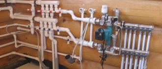
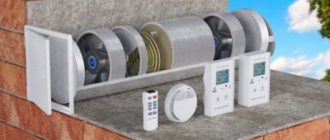
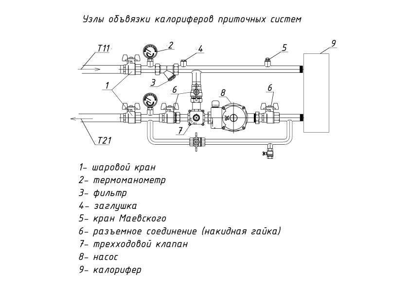
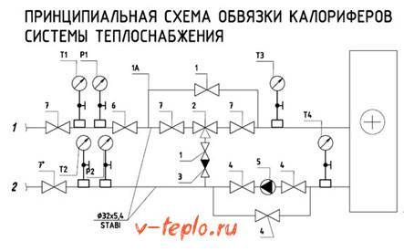
Water heater and supply ventilation piping
Many words like "mixer", "cooler device" and "connection of air heaters" confuse the inexperienced user. He only heard out of the corner of his ear about the device of the freon circuit, and he understands rather roughly what the piping units are. To learn more about heating device systems, you can "learn" on the analysis of such a unit as a water heater.

If we talk about the quantitative version, then a changing heat consumption is inevitable. This is not the best option, of course, because today the so-called good regulation principle is used. It ensures the linearity of the process, whatever the position of the control valve. Also, this principle assumes excellent resistance to possible freezing of the heating device.
With a good control principle, elements such as a centrifugal pump and a three-way piston rod valve are used. It is they that allow increasing the efficiency of the heater and strapping. They also guarantee that there can be no leaks on the floor from the steam appliance.
The principle of operation of the mixing unit
Depending on the type of heating, the work of the mixing unit is divided into two modes: qualitative and quantitative regulation. In quantitative mode, heating occurs when the flow rate of the heat carrier changes. If the flow rate does not change, the heating of the liquid occurs more evenly.
Pros of good regulation
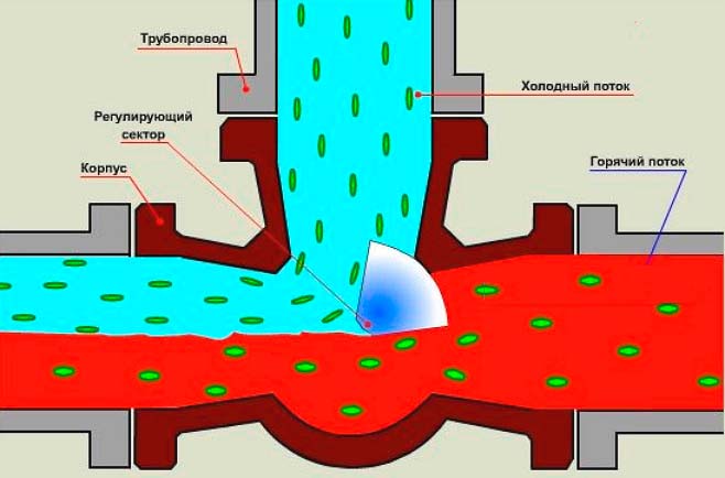
Mixing chilled water with hot water produces a valve for regulation. It is installed in front of the heater inlet. With a different position of the valve, the ratio of water of different temperatures changes, which changes the heat released by the heater. 3-way valves are often used.
Design features
Essential elements
- Air intake grille. It has both a decorative purpose and serves as a barrier for dust and other particles that wind masses contain.
- Valve. When the ventilation is turned off, the valve blocks the passage for fresh air, creating an insurmountable barrier. In winter, it can obstruct the passage of a large air flow. You can automate its work using an electric drive.
- Filters, clean the wind masses. They need to be changed every six months.
- Water, electric heater, which performs the function of heating the air.
- For small buildings, it is advisable to use an electric heater. In large rooms it is better to use a water heater.
Construction and elements

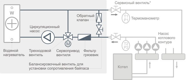
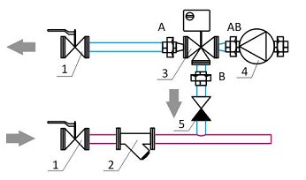
A standard mixing unit for ventilation consists of the following elements:
- 1. Connecting hoses (corrugated steel pipe)
- 2. Circulation pump
- 3. Three-way valve
- 4. Valve servo
- 5. Filter-settling tank
- 6. Check valve
- 7. Control valve for setting the bypass resistance
- 8. Service shut-off ball valves
Features of installation and connection
Installation work, connection, launching the system, setting up work - all this must be done by a team of specialists. Do-it-yourself installation of a heater is possible only in private houses, where there is no such high responsibility as in industrial premises.The main operations include installing the device and control elements, connecting them in the required order, connecting to the coolant supply and removal system, pressure testing, and test run. If all units of the complex demonstrate high-quality work, then the system is put into permanent operation.
Mixing unit: instructions for installation and configuration
What does the heater piping scheme look like?
The principle of operation can be outlined in general terms. Water, that is, a heat carrier with a high temperature, enters the heater itself, passing first a filter-sump, and then an important three-way valve. A small circulation pump is used to make the water flow at the right pressure. The water, already cooled, enters the piping, goes to the boiler, and some of its volume also enters the valve.
As for the three-code valve, it necessarily comes with the heater piping, and is considered an important regulating component. It provides the maintenance of a constant temperature and the volume of the coolant entering the heating device. When the hot water temperature rises, this valve decreases its supply while the chilled water supply increases. It turns out that the piping of the heat exchanger, without resorting to changing the water pressure in the system, changes its temperature.
Take a note:
- The control valve is the main participant in the piping of the air heater, it works in auto mode, it is controlled by an electric drive. There are various sensors in the piping set, they send signals to the electric drive, due to which the temperature is regulated and maintained at the desired level.
- Designing the strapping - there may be typical bundle schemes, which, in principle, are connected to the air heater, but still they will have to be adjusted to the device. The piping is still usually designed for any particular device.
- Options for placing straps - it can be either vertical or horizontal. But not every harness can work in every position. Therefore, the location of the piping is determined when designing the ventilation unit. Otherwise, the incorrect operation of the heating coil piping is guaranteed, or even it will refuse to work altogether.
The piping of the air heater can be built according to several schemes. In practice, however, a typical scheme is often used, the design of which is simple, and the reliability is quite high.
Mixing unit
Is the node where mixing takes place. In heating systems, this is the mixing of two different media (liquids).
In this article, we will consider only mixing units for heating systems.
Purpose of the mixing unit
- to obtain the required adjustment temperature of the coolant.
Mixing units
can be divided into two categories:
1. Sequential mixing type
2. Parallel mixing type
Sequential mixing type
is the most energy efficient and more productive type of mixing and here's why:
1. It is more efficient, because the entire pump flow goes to the circuit, which controls the temperature of the coolant. That is, depending on the parallel type of mixing in the sequential type of mixing, the entire flow goes to the circuit for which the mixing unit is intended.
2. It is energy efficient because the return heat carrier from the mixing unit has the lowest temperature. That, according to heat engineering, increases the heat transfer power. A mixing unit with a sequential type of mixing is necessarily implemented in low-temperature heating systems
Parallel mixing type
, in my opinion, is some kind of freak in the heating system. Since it is easier for any developing person at first to invent a mixing unit with a parallel type of mixing.
Disadvantages of parallel mixing type:
1. The pump flow is distributed on different sides of the mixing unit. In some mixing units, there are internal flow losses due to the peculiarities of the movement of the coolant.
2. The temperature of the coolant, from which the mixing unit is disposed of, is equal to the setting temperature of the mixing unit. Which is clearly an unreasonable approach to energy efficiency. This unit is suitable for high temperature heating systems. Where there are circuits with high temperatures.
Mixing unit with sequential mixing type, which has a central mixing.
How the Bypass Valve Works
A sequential mixing unit that has side mixing.
What is center and side mixing is written here:
Mixing unit with a parallel type of mixing, in which the valve has a center or side mixing.
Mixing unit with parallel mixing type, which has side mixing.
Mixing unit with double mixing
In such a mixing unit scheme, there are two mixing units and it can be safely called a double mixing unit.
Mixing takes place in two places:
The pump flow is distributed in three circuits: (C1-C2), (C3-C4), (Line 1)
The cheapest and least energy efficient mixing unit of the brand:
Watts IsoTherm
This unit is designed for warm water floors. Suitable for high temperature heating systems. For example, if there is radiator heating (not lower than 60 degrees), and warm water floors, for which the coolant temperature is calculated not higher than 50 degrees. That is, the input always requires a higher temperature than the setting temperature.
Condition T1> T2
... It is impossible that T1 = T2. This condition applies to all mixing assemblies with a parallel mixing type. Again, such a node is not suitable for low temperatures.
The sequential mixing unit with a 3-way center mixing valve has the most energy efficient performance.
Example of an energy efficient mixing unit
Such a mixing unit may have a condition when the temperature is C1 = C3
Mixing unit DualMix
by Valtec
The Dualmix is a parallel mixing type that comes with a 3-way side mixing valve as standard.
CombiMix mixing unit
by Valtec
Mixing unit CombiMix
is a sequential blending type, but it is side blending. Unfortunately, such a mixing unit is not suitable for low temperatures. That is, the inlet temperature must be higher than the setpoint temperature of the assembly.
Lack of a mixing unit CombiMix
is that this mixing unit is side mixing.And for low-temperature heating systems, mixing units are suitable, in which there is a three-way valve with central mixing.
Find out more about valves and mixing types here:
By the way ready mixing units FAR (TERMO-FAR)
fully meet the energy efficiency requirements.
This unit has a center mixing thermostatic mixer. That is, when the hot passage is closed, the cold passage opens at the same time. Each of the two aisles can be completely closed separately. Only such a three-way valve can be energy efficient. In any case, find out the detailed work of three-way valves. Because they can slip a valve with side mixing and then the pipe is the case ...
Commercially available, these usually have three-way center mixing valves that allow for the same setpoint and inlet temperature.
For example,
To obtain mixing assemblies, you can use various valves in more detail here:
How servos and 3-way valves work
This concludes the article, write your comments.
| Like |
| Share this |
| Comments (1) (+) [Read / Add] |
A series of video tutorials on a private house
Part 1. Where to drill a well? Part 2. Arrangement of a well for water Part 3. Laying a pipeline from a well to a house Part 4. Automatic water supply
Water supply
Private house water supply. Principle of operation. Connection diagram Self-priming surface pumps. Principle of operation. Connection diagram Calculation of a self-priming pump Calculation of diameters from central water supply Pumping station of water supply How to choose a pump for a well? Setting the pressure switch Pressure switch electrical circuit Principle of operation of the accumulator Sewer slope by 1 meter SNIP Connecting a heated towel rail
Heating schemes
Hydraulic calculation of a two-pipe heating system Hydraulic calculation of a two-pipe associated heating system Tichelman loop Hydraulic calculation of a single-pipe heating system Hydraulic calculation of a radial distribution of a heating system Scheme with a heat pump and a solid fuel boiler - logic of operation Three-way valve from valtec + thermal head with a remote sensor Why does the heating radiator in an apartment building do not heat well? home How to connect a boiler to a boiler? Connection options and diagrams DHW recirculation. Principle of operation and calculation You do not correctly calculate the hydraulic arrow and collectors Manual hydraulic calculation of heating Calculation of a warm water floor and mixing units Three-way valve with a servo drive for DHW Calculations of DHW, BKN. We find the volume, power of the snake, warm-up time, etc.
Water supply and heating constructor
Bernoulli's equation Calculation of water supply for apartment buildings
Automation
How servos and three-way valves work Three-way valve to redirect the flow of the heating medium
Heating
Calculation of the heat output of heating radiators Radiator section Overgrowth and deposits in pipes impair the operation of the water supply and heating system New pumps work differently ... Calculation of infiltration Calculation of temperature in an unheated room Calculation of the floor on the ground Calculation of a heat accumulator Calculation of a heat accumulator for a solid fuel boiler Calculation of a heat accumulator for accumulating heat energy Where connect an expansion tank in the heating system? Boiler resistance Tichelman loop pipe diameter How to choose a pipe diameter for heating Heat transfer of a pipe Gravitational heating from a polypropylene pipe Why do they not like single-pipe heating? How to love her?
Heat regulators
Room thermostat - how it works
Mixing unit
What is a mixing unit? Types of mixing units for heating
System characteristics and parameters
Local hydraulic resistance. What is CCM? Throughput Kvs. What it is? Boiling water under pressure - what will happen? What is hysteresis in temperatures and pressures? What is infiltration? What are DN, DN and PN? Plumbers and engineers need to know these parameters! Hydraulic meanings, concepts and calculation of heating systems circuits Flow coefficient in a one-pipe heating system
Video
Heating Automatic temperature control Simple top-up of the heating system Heating technology. Walling. Underfloor heating Combimix pump and mixing unit Why choose underfloor heating? Water heat-insulated floor VALTEC. Video seminar Pipe for underfloor heating - what to choose? Warm water floor - theory, advantages and disadvantages Laying a warm water floor - theory and rules Warm floors in a wooden house. Dry warm floor. Warm Water Floor Pie - Theory and Calculation News to Plumbers and Plumbing Engineers Are you still doing the hack? First results of the development of a new program with realistic three-dimensional graphics Thermal calculation program. The second result of the development of Teplo-Raschet 3D Program for thermal calculation of a house through enclosing structures Results of the development of a new program for hydraulic calculation Primary secondary rings of the heating system One pump for radiators and underfloor heating Calculation of heat loss at home - orientation of the wall?
Regulations
Regulatory requirements for the design of boiler rooms Abbreviated designations
Terms and Definitions
Basement, basement, floor Boiler rooms
Documentary water supply
Sources of water supply Physical properties of natural water Chemical composition of natural water Bacterial water pollution Requirements for water quality
Collection of questions
Is it possible to place a gas boiler room in the basement of a residential building? Is it possible to attach a boiler room to a residential building? Is it possible to place a gas boiler room on the roof of a residential building? How are boiler rooms divided according to their location?
Personal experiences of hydraulics and heat engineering
Introduction and acquaintance. Part 1 Hydraulic resistance of the thermostatic valve Hydraulic resistance of the filter flask
Video course Calculation programs
Technotronic8 - Hydraulic and thermal calculation software Auto-Snab 3D - Hydraulic calculation in 3D space
Useful materials Useful literature
Hydrostatics and hydrodynamics
Hydraulic Calculation Tasks
Head loss in a straight pipe section How does head loss affect the flow rate?
Miscellaneous
Do-it-yourself water supply of a private house Autonomous water supply Autonomous water supply scheme Automatic water supply scheme Private house water supply scheme
Privacy Policy
Air heater operating rules
For the correct and uninterrupted operation of heaters for supply ventilation systems, it is important to observe the following operating rules:
- It is necessary to maintain a certain composition of the air in the building. Requirements for air masses in rooms for various purposes are listed in GOST No. 2.1.005-88.
- During installation, you must follow the manufacturer's recommendations, adhere to the installation technology.
- Do not supply a coolant with a temperature above 190 degrees to the device. For some models, this threshold is less than what is stated in the technical documentation.
- The pressure of the liquid medium in the heat exchanger should be within 1.2 MPa.
- If you need to heat the air in a cold room, then it is heated smoothly. The temperature rise within an hour should be 30 degrees.
- To prevent the liquid from freezing in the heat exchanger and breaking the tubes, the surrounding air masses around the device must not be allowed to cool below zero degrees.
- In a room with a high level of humidity, units with a degree of protection from IP66 and higher are installed.
Manufacturers of water heaters do not recommend repairing them yourself. It is better to entrust this work to the employees of the service center
It is equally important to correctly calculate the power of the device before buying so that it provides the proper performance and does not idle.
Scheme of work
The air temperature in the duct is regulated by limiting the supply of hot (cold) water to the water heat exchanger using a three-way valve.
The mixing unit works as follows. With an increase in the set air temperature in the air channel, the position of the stem in the three-way valve changes, it closes, and the coolant (water) is supplied to the heat exchanger in a smaller amount or completely closed (depending on the applied drive), passing along a small circuit - bypass. When the air temperature drops, the three-way valve opens and the coolant flows into the heat exchanger in a “big circle”.
Mixing unit diagram for a heat exchanger
Operating conditions of the mixing unit:
- The maximum temperature of the coolant is 110oC;
- The maximum pressure of the coolant is 1 MPa;
- The coolant (water) must not contain solid impurities and aggressive chemicals that contribute to corrosion and decomposition of the materials of the unit parts;
- The ambient temperature during the operation of the unit must be higher than the freezing temperature of the coolant.
Where is it applied?
- Supply units with a water heater;
- Air handling units with a water heater;
- Supply and supply and exhaust installations in a water air cooler;
- In type-setting ventilation systems;
- Heat guns with water heating;
- Thermal curtains with water heating;
- Fan coil units;
- Water floors, etc.
For reliable operation of the mixing unit and prevention of defrosting of heat exchange equipment in winter, as well as during operation, it is necessary:
- Clean the working surface of the unit once a year;
- Periodically (depending on operating conditions) clean the filter;
- To reduce salt precipitation, specially prepared water from the central water supply networks should be used.
The pump motor and the three-way valve motor do not require maintenance!
Types of heat consumption systems
There may be several such systems compatible with the heater. Let's take a quick look at each one.
Ventilation system
It is characterized by the fact that the technical parameters of the existing equipment directly affect the limiting temperature of the coolant. The problem with how to choose the correct piping unit is the need to protect the air heater from possible freezing. In winter, when air will be supplied with a subzero temperature, it is impossible to reduce the temperature of the heat carrier or the energy consumption is lower than required by the system.
Radiator heating
In this case, the temperature of the coolant is strictly limited. For one-pipe structures it is 105 degrees, for two-pipe structures it is 95 degrees. But the temperature of the carrier can drop indefinitely, up to the termination of work altogether, which distinguishes heating from a ventilation system. Here, all the elements are in direct contact with the air in the building, and due to the fact that it also has heat storage characteristics, the building cools rather slowly. In this case, the time period during which a temperature decrease is possible is set for each individual case.
Underfloor heating
Heat consumption here is the same as in the previous version. The only difference is that the temperature of the heat carrier (maximum) is limited. In most cases, this is no more than 50 degrees.
Thermal curtain
The piping of the air heater for heat curtains differs significantly from all previous options, so we will consider it in more detail.First of all, this refers to the peculiarities of the operation of the thermal curtain itself: almost all the time the curtain "rests", expects, its working time often does not exceed two or three minutes. Moreover, the installation site is always located far from the heating source. In most cases, this is a place under the ceiling, and there, accordingly, hypothermia often occurs, as well as drafts. Below is a diagram with adjusting elements that are suitable for this case.
The system is equipped with special ball joints necessary to disconnect it from the described curtain or from the heating route. There is also a roughly cleanable filter that protects the device; a control valve that prevents the ingress of solid particles, which, in turn, can have an extremely negative effect on the overall performance of the system. There are two more valves:
- Regulating shut-off.
- Regulating, equipped with a special drive.
Each of them is designed to provide maximum fluid flow during operation, and minimum when “inactive”. In order for the valve actuators of such a piping intended for thermal curtains to be provided with proper power, a single-phase voltage of 220 volts should be connected.
Finally, all the elements that make up the piping of the heater in this case are necessary not only to regulate the temperature in the building, but in order to protect the device itself from temperature drops, pressure "jumps" that often occur in the heating network. If you install mixing blocks, then the heating circuit will enter the operating mode that is necessary for the monitored parameters.
Note! Ventilation works more efficiently in this regard, since less energy is consumed.
Mixing unit device underfloor heating
The main element of the mixing unit for heating is the valve, which is responsible for mixing the heat carriers. It can be two-way or three-way.
The two-way valve consists of a thermostat head, inside which a liquid sensor is placed. This sensor, when supplying a coolant, records its temperature. If it exceeds the norm, then the head rotates, thereby closing the entrance to the circuit. Usually, the cooled liquid from the return is always open. Hot coolant is passed to the pipes only when the temperature of the warm floor drops. The two-way valve copes well with the system of a small room, because it passes the coolant through only one circuit.
If you need to heat an apartment of more than 200 square meters, then you need to use a three-way valve (the two-way valve has a low throughput). Such a valve has three connections, i.e. it serves not one, but several circuits. It mixes hot and cold water. It also redistributes flows with liquid of different temperatures. The three-way valve is equipped with a servo drive, which regulates its operation.
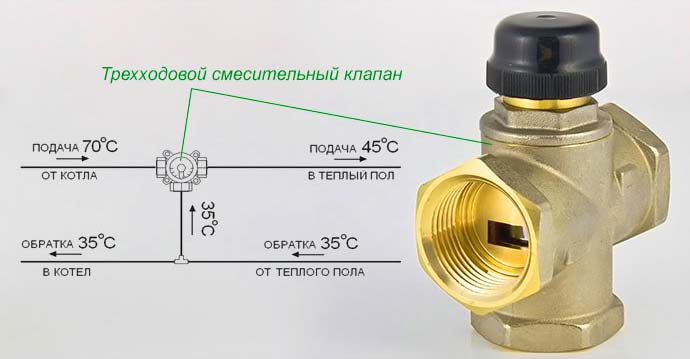
The main part of this part of the system is a damper, which is installed so that water is mixed in a certain amount when the flows of cold and hot heat carrier intersect. It can be adjusted according to the norms. You can move the damper to the other side, thereby increasing the flow of hot water if the outside temperature has dropped. It is located at the meeting point of hot and cold streams near the boiler. Unlike the two-way valve, the hot water supply does not shut off. The amount of hot and cold coolant depends on the position of the damper: what kind of water it passes through in a larger ratio, and what in a smaller one. Mixing, the flows form a heat carrier of a certain temperature.
The underfloor heating also includes weather-dependent sensors.
If the air temperature rises, the cold water supply may increase.
With a decrease in temperature in cold weather, the flow of hot water can increase its intensity.
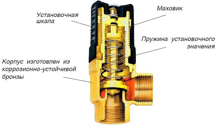
An important part of the system is the secondary circuit balancing valve. It mixes hot water in the supply pipe and cold water in the proportions required for heating.
The scale on the valve indicates the throughput of the valve. In order not to accidentally change the position of the balancing valve, it is fixed with a clamping wrench. A hex wrench can be used to change the setting of the valve.
The bypass valve protects the circulation pump from damage due to a pressure drop that occurs from accidentally stopping the flow of water through the pump.
Its purpose is to maintain water pressure. When it falls, the valve is triggered. As a result, hot water flows through the bypass (backup path in emergency condition) to the central heating batteries.
How the heating of the air heater is regulated
In order to control the warm-up procedure taking place in the piping unit of the device, you can use one of two possible methods:
- quantitative;
- high quality.
If you choose the quantitative control of the system operation, then you will face the inevitable and constantly "jumping" consumption of the heat carrier. This method can hardly be called rational, and this is one of the reasons that in recent years people have often resorted to another principle of control - quality. Thanks to him, it became possible to regulate the operation of the heater, but the amount of coolant does not change at all.
In addition, if you regulate the system through a quality principle, then the control is guaranteed to remain linear, no matter what position the control valve is in.
Important! Quality control has one more advantage - so the heater will be maximally protected from possible freezing, since water will constantly flow into it. All this became possible only due to the fact that a water pump is installed in the heater circuit.
A water flow is carried out in the circuit, which will not depend on any external influences. In addition, quality control involves the use of a three-stroke stem valve and a dedicated pump. All these parts built into the piping of the device have significant advantages that increase the efficiency of the heater and the entire system as a whole:
All this became possible only due to the fact that a water pump is installed in the heater circuit. A water flow is carried out in the circuit, which will not depend on any external influences. In addition, quality control involves the use of a three-way stem valve and a dedicated pump. All these parts built into the piping of the device have significant advantages that increase the efficiency of the heater and the entire system as a whole:
- The regulation valve is located in the place where the heat carrier enters the heater. Compared to a two-stroke device, it controls the entire mixing procedure. If the circuit is closed, then internal circulation occurs; if it is open, then the coolant does not recirculate. If a similar design is installed with a stem, then this will not only increase the life of the valve itself (which, as you know, becomes unusable very quickly in products that do not have stems), but also increase heat transfer.
- The motor of the centrifugal circulation pump is "wet"; in other words, it operates completely submerged in water. Consequently, the bearings of the device, as well as other elements, are constantly lubricated with water, so there is no need to use any kind of oil seals.If the piping of the heater is equipped with such a pump, then leakage is completely excluded, even in cases where the pump is broken or has completely exhausted its resource.
Mixing unit for water heater
Ventilation units with a water heater are completed with a mixing unit containing a two- or three-way valve.
Mixing unit diagram with a three-way valve
Mixing unit diagram with a two-way valve
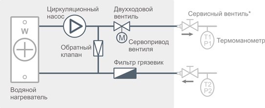
| * | Service valves must be connected to the mixing unit using American connectors in order to be able to dismantle the ventilation unit. Service valves and thermomanometers are installed in accordance with the heat supply project and are not part of the mixing unit. |
Choice of valve type
The choice of the type of valve is determined by the parameters of the heat supply system. In general, for ventilation units connected to a separate circuit of an autonomous heating system (for example, to a gas boiler in a cottage), a unit with a three-way valve is required; for air handling units connected to a central heating system, a two-way valve assembly is required.
To determine the required type of valve and to accurately calculate the mixing unit, information is needed on the parameters of the heat supply system:
- System type (central / autonomous).
- Direct and return water temperatures.
- For the central system: pressure drop between the "direct" and "return" water pipes.
- For an autonomous system: the presence or absence of a separate pump in the supply ventilation circuit.
Calculation of the diameter of the supply pipes
The calculation is based on the maximum permissible water velocity in the pipe and is applicable for routes up to 30 m long. For longer routes, it is necessary to perform a hydraulic calculation to select the pump and the pipe diameter.
| Du, mm | G max, t / hour | V max, m / s | ΔР per 1 running meter, Pa | Q kW, at ΔT of water: | ||
| 20 ° C | 40 ° C | 60 ° C | ||||
| 15 | 0,43 | 0,68 | 480 | 10 | 20 | 30 |
| 20 | 0,77 | 0,68 | 340 | 18 | 36 | 54 |
| 25 | 1,2 | 0,68 | 250 | 28 | 56 | 84 |
| 32 | 2 | 0,7 | 190 | 47 | 93 | 140 |
| 40 | 3,2 | 0,7 | 150 | 76 | 149 | 224 |
| 50 | 4,9 | 0,7 | 110 | 114 | 228 | 347 |
Du - nominal bore diameter, mm. G max, t / hour - water consumption (tons / hour) at the maximum allowable speed Vmax. V max, m / s - the maximum permissible water velocity. ΔР, Pa - water pressure loss per one running meter of the pipe at Vmax. ΔТ, ° C - temperature difference between direct and return water. Q, kW - power taken from the water.
Power required to heat the air to the set temperature:
| L *, m³ / hour | Required power at an air flow rate L for heating air from Tvh = -28 ° C to Tvh: | ||||
| 20 ° C | 25 ° C | 30 ° C | 35 ° C | 40 ° C | |
| 500 | 8,1 | 8,95 | 9,75 | 10,6 | 11,45 |
| 1000 | 16,2 | 17,9 | 19,5 | 21,2 | 22,9 |
| 2000 | 32,4 | 35,8 | 39 | 42,4 | 45,8 |
| 3000 | 48,6 | 53,7 | 58,5 | 63,6 | 68,7 |
| 4000 | 64,8 | 71,6 | 78 | 84,8 | 91,6 |
| 5000 | 81 | 89,5 | 97,5 | 106 | 114,5 |
| 6000 | 97,2 | 107,4 | 117 | 127,2 | 137,4 |
| 7000 | 113,4 | 125,3 | 136,5 | 148,4 | 160,3 |
| 8000 | 129,6 | 143,2 | 156 | 169,6 | 183,2 |
| 9000 | 145,8 | 161,1 | 175,5 | 190,8 | 206,1 |
| 10000 | 162 | 179 | 195 | 212 | 229 |
| 11000 | 178,2 | 196,9 | 214,5 | 233,2 | 251,9 |
| 12000 | 194,4 | 214,8 | 234 | 254,4 | 274,8 |
| 13000 | 210,6 | 232,7 | 253,5 | 275,6 | 297,7 |
| 14000 | 226,8 | 250,6 | 273 | 296,8 | 320,6 |
| 15000 | 243 | 268,5 | 292,5 | 318 | 343,5 |
| 16000 | 259,2 | 286,4 | 312 | 339,2 | 366,4 |
| * | L is the volumetric flow rate of "standard air" (standard conditions: t = 20 ° C, φ = 0%, P = 760 mm Hg). |
Heat carrier consumption
To calculate the flow rate of the heat carrier, you first need to find the frontal section of the device.
It is determined by the formula F = (L x P) / V, in which:
- F - frontal section of the air heater heat exchanger;
- L is the flow rate of air masses;
- P - tabular value of air density;
- V - air flow speed (3-5 kg / m²).
After that, you can calculate the flow rate of the coolant by the formula G = (3.6 x Qt) / (Cw x (tin - tout)), in which:
- G - water demand for the heater (kg / h);
- 3.6 - a correction factor for converting a unit of measurement from Watt to kJ / h, so that the flow rate is obtained in kg / h;
- Qt is the heater power in W, which was found earlier;
- Cw - indicator of the specific thermal capacity of water;
- (tin - tout) - temperature difference of the heat carrier in the return and straight lines.
A brief overview of modern models
To get an impression of the brands and models of water heaters, consider several devices from different manufacturers.
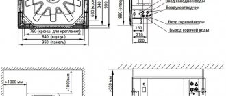
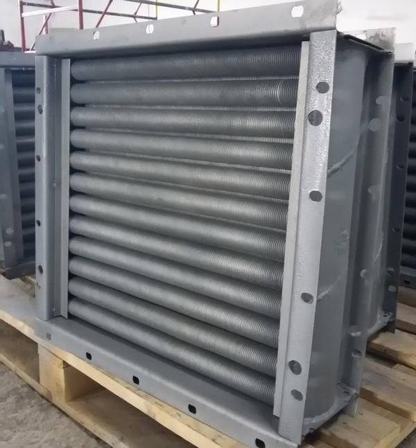
Heaters KSK-3, manufactured at the CJSC T.S.T.
Specifications:
- coolant temperature at the inlet (outlet) - + 150 ° С (+ 70 ° С);
- inlet air temperature - from -20 ° С;
- working pressure - 1.2 MPa;
- maximum temperature - + 190 ° С;
- service life - 11 years;
- working resource - 13,200 hours.
The outer parts are made of carbon steel, the heating elements are made of aluminum.
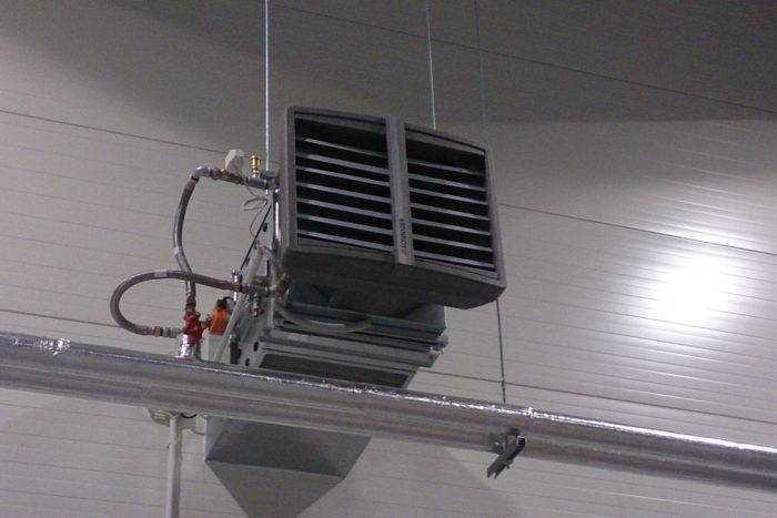
The Volcano mini water heater is a compact device from the Polish brand Volcano, distinguished by its practicality and ergonomic design. The air flow direction is adjusted using controlled louvers.
Specifications:
- power in the range of 3-20 kW;
- maximum productivity 2000 m3 / h;
- heat exchanger type - double row;
- protection class - IP 44;
- the maximum temperature of the coolant is 120 ° C;
- maximum working pressure 1.6 MPa;
- internal volume of the heat exchanger 1.12 l;
- guide blinds.
Heater Galletti AREO made in Italy. Models are equipped with a fan, copper-aluminum heat exchanger and drain pan.
Specifications:
- heating power - from 8 kW to 130 kW;
- cooling power - from 3 kW to 40 kW;
- water temperature - + 7 ° C + 95 ° C;
- air temperature - 10 ° C + 40 ° C;
- working pressure - 10 bar;
- the number of fan speeds - 2/3;
- electrical safety class IP 55;
- protection of the electric motor.
In addition to the devices of the listed brands, on the market of air heaters and water air heaters, you can find models of the following brands: Teplomash, 2VV, Fraccaro, Yahtec, Tecnoclima, Kroll, Pakole, Innovent, Remko, Zilon.
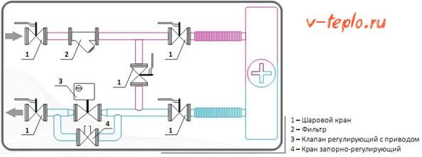
Methods for piping a heater
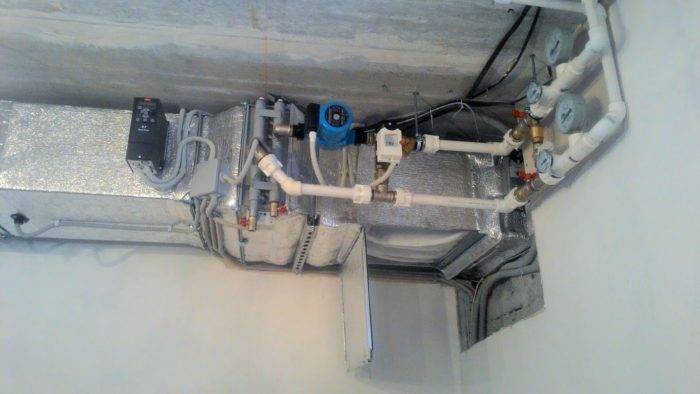
The piping of the supply ventilation heater depends on the choice of the installation site, the technical characteristics of the unit and the air exchange scheme. Among the different installation options, mixing of recirculated air masses with supply flows is most often used. Less commonly, a closed circuit with air recirculation within the premises is used.
For the correct installation of the appliance, it is important that the natural ventilation system is well established. The connection of the heater to the heating network is usually done at the point of intake within the basement.
If there is forced ventilation, then the unit can be installed in any suitable location.
Also on sale there are ready-made strapping units in several versions.
The kit includes the following items:
- ball valves with bypass;
- check valves;
- balancing valve;
- pump equipment;
- two or three way valves;
- filters;
- manometers.
These parts in the assembly can be combined in different ways. Apply rigid connection of elements or installation using flexible metal hoses.
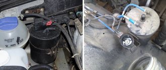
Schemes and types of executions of mixing units UTK


The mixing unit is built according to a three-way control scheme
There is a filter 2 for hot water on the supply line of the unit. As soon as it gets dirty, it is necessary to clean the filter element.
Adjusting the heating process
As for the regulation of the heating process, today two types of it are used: quantitative and qualitative. The first option is when the temperature of the heating elements is regulated by the amount of heat energy supplied to them. That is, the more, for example, hot water passes through the water heater, the more it heats up. Accordingly, the temperature of the air passing through it becomes higher.
To do this, a pump must be included in the piping unit of the air heater of the air handling unit, which creates pressure inside the hot water supply system. By increasing the flow, you can increase the temperature of the coolant inside the heating elements. Or, conversely, by reducing the flow, the temperature regime decreases.It should be noted that this method of heating the supply air is not the most rational. Therefore, today, more and more often, a high-quality heating method is used in ventilation systems, that is, hot water is supplied with its volume unchanged.
A purely constructive distinctive feature of this piping scheme is the presence of a three-way valve, which is installed near the heating device before hot water is supplied to it. It is the valve that regulates the temperature, and the pump operates in a constant mode. The valve got its name due to the fact that it can be set in certain positions in which different processes take place. In the case of air heating, the valve performs three functions.
- It is completely open for hot water supply and closed for the heat transfer medium from the heater.
- It is open so that part of the cooled coolant can mix with hot water, thereby reducing its temperature, and, accordingly, of the heating elements.
- Completely closed, that is, no heating medium enters the supply air heating system.
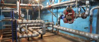
Schemes and types of execution of piping units for water coolers UTO
For the manufacture of piping assemblies used fittings of the company Genebre (Spain), pumps WILO, GRUNDFOS and UNIPAMP (Germany), Actuators with a three-way valve from ESBE (Sweden)
Main function thermal control units UTZ - together with the control system, control and regulate the temperature of the coolant in the water heaters of the air curtains. Thermal control units for thermal curtains are called differently - strapping units thermal curtains.
Quality of work: piping unit for the air heater of the air handling unit
There are 2 ways of mounting the device, which are determined by the heat transfer scheme. If we talk about natural ventilation, with it, the heater should be located in the basement near the water intake point. With a forced ventilation system, the device will competently begin to function only with the correct installation of the piping of the heating module.
These devices allow you to adjust the temperature level of the heat exchanger:
- Bypass;
- Eyeliner;
- Cleaning filter;
- Pump;
- Ball Valves;
- Thermometers and manometers;
- Motorized valve.
If we are talking about the installation of a piping unit with a rigid connection, the communications will be carried out using steel pipes. Sometimes for installations, a flexible hose with corrugated hoses in the system is also used. The site of the node is determined in advance. Tying the knot does not imply any serious costs.
Structure
- Circulation pump - ensures the passage of liquid through the heat exchanger and the pipeline network;
- Three-way valve (less often two-way) - provides the direction of fluid movement into the heat exchanger, or bypassing it, letting the coolant through the bypass, along the “small circuit”;
- Electric actuator - a drive mechanism for flow control, installed directly on a three-way valve using a mounting kit;
- Check valve - prevents the coolant from flowing into the counterflow;
- Coarse filter - for cleaning the coolant from metal inclusions, to prevent valve jamming, heat exchanger pollution.
If necessary, the mixing unit for ventilation can also be equipped with:
- Ball valves - to limit the supply of coolant to the circuit of the mixing unit and heat exchanger;
- Thermomanometers - necessary for visual control of the temperature and pressure in the circuit. Example: thermomanometer assembly Aeroblock TM 25-MST or TM 32-MST;
- Balancing taps - to adjust the water flow;
- Flexible hose - for ease of installation.
Supply ventilation with water heated air
Air heating to the required temperature is provided by a water heater.It is presented in the form of a radiator with tubes in which the coolant is located. The piping has ribbing, which increases the area of contact with the circulated air.
The principle of operation of the system is as follows: the coolant heats the tubes to the required temperature, they give off heat to the ribbing, which in turn heats the air. Thus, heat exchange is carried out.
Supply ventilation with water heated air is much more profitable than heating using electricity. On the other hand, there is water inside the water heater, so there is a risk of freezing with minimal radiator operation.
The power of such a device is regulated by electrical and plumbing components.
- Zone with controller and temperature sensors. Valve control servo.
- A mixer, it is responsible for heating water in heating equipment to the required temperature.
The electrical component will control the plumbing unit. It is enough to set the required temperature for heating the air, and the system will carry out this program.
How to choose
When choosing a unit for ventilation, you need to pay attention to several conditions.
Smooth control
This requirement is expressed in the fact that the position of the valve, which regulates the water supply, the amount of water changes uniformly, without sudden jumps. That is, the amount of coolant that comes from the external and return circuits changes in proportion to the rotation of the valve handle.
This can be achieved by choosing a valve with a resistance equal to or greater than the hydraulic resistance of the rest of the circuit. When choosing, you should pay attention to the throughput of the valve - Kvs, which is indicated by the manufacturer. The formula for calculating pressure loss is as follows:
dP = (G / Kvs), Bar
where G is the flow rate in m3
If the valve is selected incorrectly and its Kvs is too high, then the unit will behave unstable, up to failure.
Optimal operating point selection
To achieve this goal, a circulation pump is used, the power of which ensures the circulation of the coolant along the internal circuit. The pump power must be such as to compensate for the pressure loss in the system and ensure normal circulation. When choosing a pump, they are guided by the pressure-flow characteristic, which is presented in the form of graphs. Depending on the performance, the pump should be selected to match the operating point of the entire system, avoiding excess or missing power.
What are the heaters
The device can be installed in one of two ways, in this case it all depends on the characteristics of the system's air exchange.
- The recirculated air can be mixed with the supply air.
- The air in the system can be recirculated while being completely isolated.
If the ventilation in the room is natural, then the heater should be located in the basement, in the place where the air is drawn in. And if the ventilation scheme is forced, then it does not matter where the device will be installed.
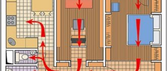
Automated air heating in supply ventilation
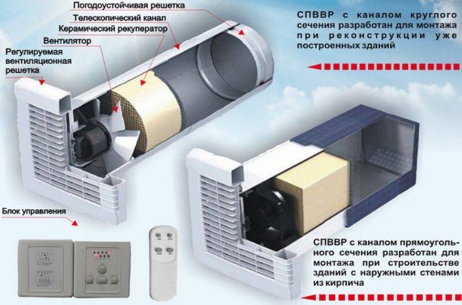
Options for the device of round and rectangular ventilation shafts - the system is automated
- The operation of the equipment is controlled by a control panel (CP). The user presets the control mode for the supply air flow and temperature.
- The timer switches the heated ventilation system on and off automatically.
- Equipment that provides heating can be connected to an exhaust fan.
- The heaters are supplied with a thermostat, which prevents the occurrence of a fire.
- A pressure gauge is installed in the ventilation system to control pressure drops.
- A shut-off valve is installed on the supply ventilation pipe, it is designed to block the flow of supply wind masses.
(no votes yet)