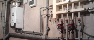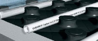
What is a comb for?
What constitutes the functionality and efficiency of a heating system? It must provide a comfortable temperature in all areas of the house and the necessary heating of water. In addition, it must be safe during operation and as maintainable as possible.
One of the functions of the comb is the ability to turn off the supply of coolant to a separate circuit of the heating system. This allows you to carry out repair work without turning off the heating as a whole.
All these conditions of normal operation can be solved by a functional element of the collector (beam) heating wiring diagram, which is called a collector or a comb. For example, in the house suddenly, as it often happens, a radiator or pipe joints leaked. If there is a comb, this local problem can be solved without turning off all the heating. It is enough, simply by shutting off the desired valve, to turn off only the area that needs repair.
In addition, one collector, which is installed on the entire heating system of the cottage, will perfectly cope with the function of controlling the heating process. He will also be able to adjust the temperature in every room of the house. The use of this device allows you to control the heating system quite efficiently and simply. At the same time, the costs of manpower and resources are minimized.
https://youtu.be/CCLJyz-V-w8
Both the distributor and the regulator
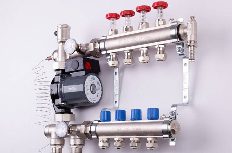
At its core, a manifold is a centralized unit that allows the coolant to be distributed to its destination. In the heating system, it performs no less important function than a circulation pump or the same boiler. It distributes the heated water through the mains and regulates the temperature.
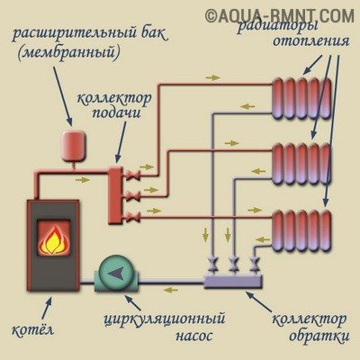
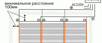
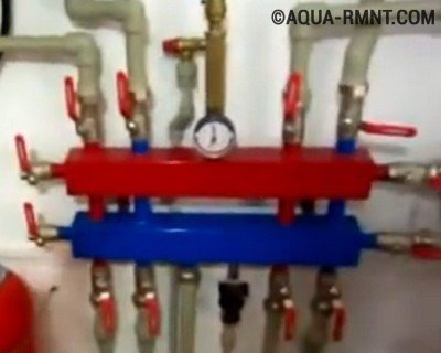
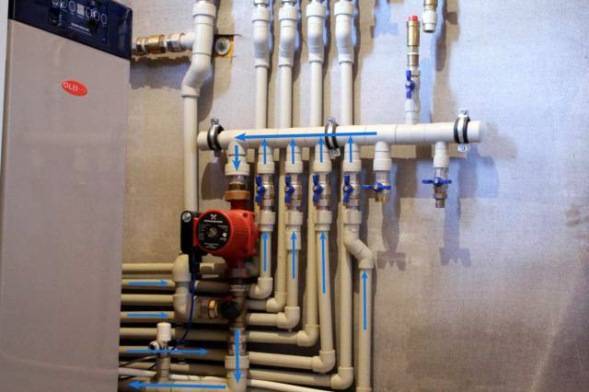
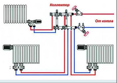
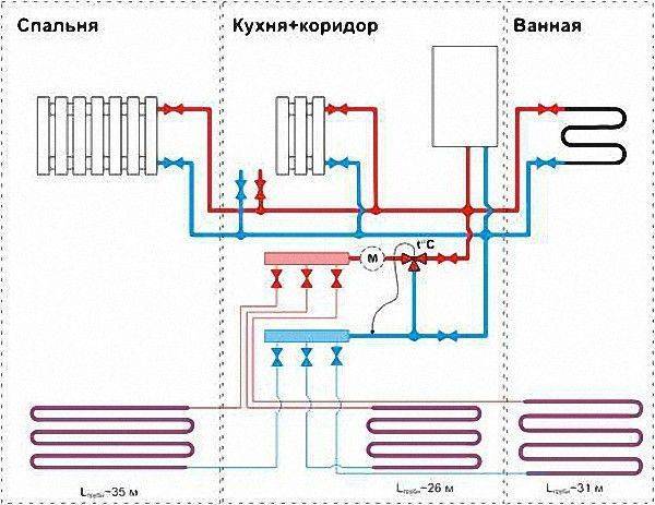
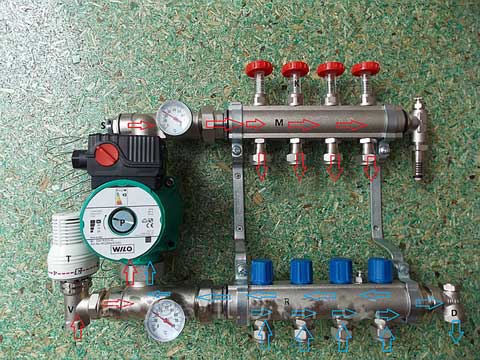
This diagram shows the general principle of operation of the collector block, consisting of two combs: through one, the coolant is supplied to the system, and through the second it is returned
This unit can be called a temporary coolant storage. It can be compared to a barrel filled with water, from which the liquid flows out not through one hole, but through several. In this case, the pressure of the water flowing out of all the holes is the same. This ability to provide a uniform distribution of the heated liquid at the same time is the main principle of the device.
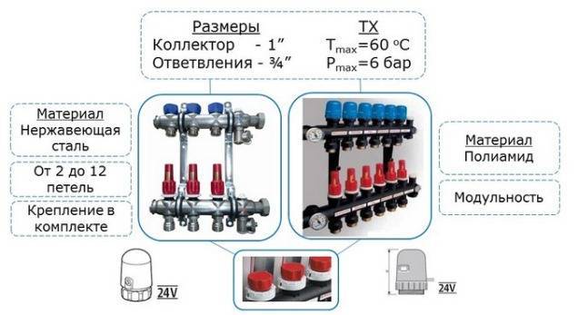
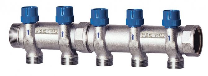
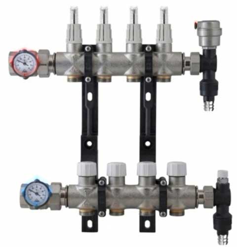
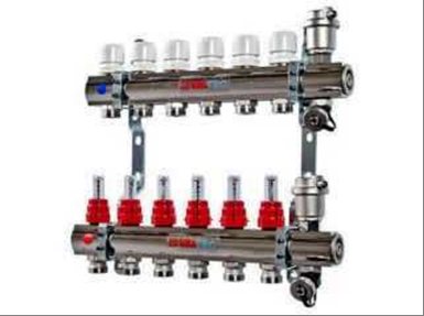
Externally, the collector looks like a two-comb assembly, made, most often, of stainless steel or ferrous metal. The outputs available in it are designed to connect heating devices with it. The number of such terminals must correspond to the number of serviced heating devices. If the number of these devices increases, the node can be increased, so the device can be considered dimensionless.
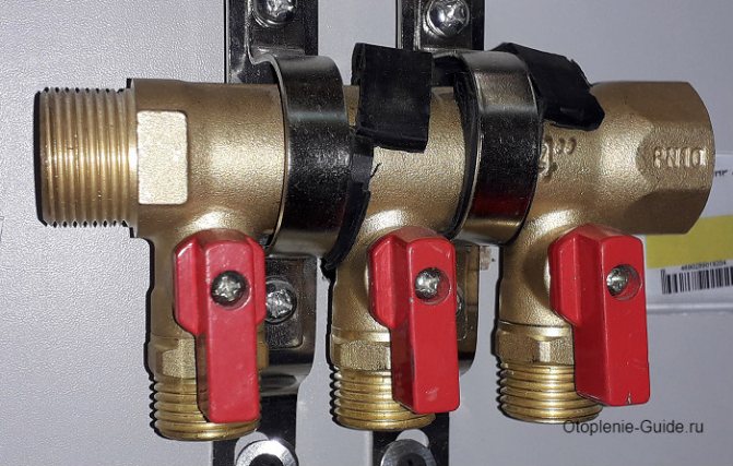
In addition to the terminals, each comb is equipped with locking mechanisms. These can be of two types, installed at the outlet:
- Cut-off. Such taps allow you to completely stop the supply of coolant from the general system to its individual circuits.
- Adjusting. With the help of these taps, the volume of water supplied to the circuits can be reduced or increased.
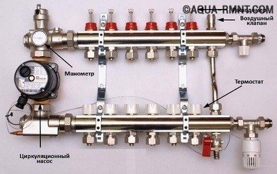
The manifold includes water drain and air release valves. Here it is most convenient to arrange the measuring equipment in the form of heat control meters. In this case, everything that is necessary for the effective operation of this node will be in one place.
Why does the manifold block include two manifolds? One serves to supply the coolant to the circuits, and the second is responsible for collecting already cooled water (return) from the same circuits. All elements necessary for effective functioning must be on each of the combs.
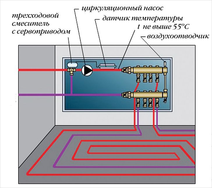
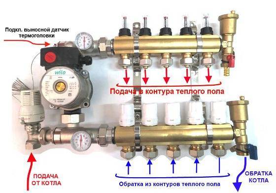
Working principle with a three-way regulator
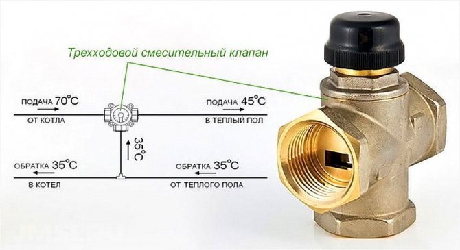
A smoother heating process of the circuits occurs when the connection of the underfloor heating comb is carried out through a three-way valve... In this case, the distribution unit has three connection points: from the boiler heater, the supply manifold, and the inlet of the cooled heat carrier.
In the initial position, the regulator is open only to supply hot water from the boiler. When its temperature exceeds the required value, the regulator will partially open the underfloor heating system and slightly close the connection to the boiler.
Then the hot and cooled water will mix. The regulator will remain in this position until the temperature drops below the required value. When this happens, the valve will close the underfloor heating circuit and completely open the boiler supply.
This work cycle repeats continuously. This heating method is usually used for large areas exceeding 150 m². But it is believed that the three-way regulator is less reliable and more likely to fail.
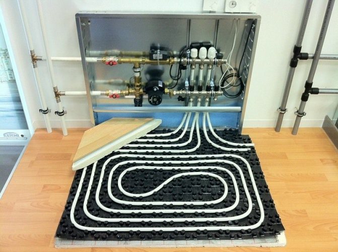
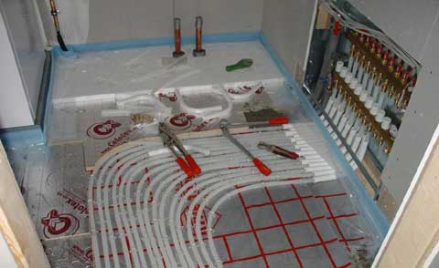
How to assemble a comb for underfloor heating
I must say that assembling the comb with your own hands is a very real task. If you have installed the heating system in your house yourself, then you have enough skills to assemble this unit. Moreover, factory-made combs are supplied in a set and they are accompanied by installation instructions with diagrams and explanations. An example of such a scheme is presented below:
At the moment, distribution units are made of the following materials:
- brass;
- stainless steel;
- plastic (polyamide).
Factory comb made of plastic is truly a godsend, its cost is much less than that of metal "brothers". Moreover, in practice, it functions no worse, in any case, there are very few negative reviews about it. The assembly of a distributor from any material consists in connecting the comb sections to each other, screwing a mixing unit from a pump with a valve to them, installing thermometers, taps and air vents. The finished manifold can be installed in place and pipes can be connected to it.
For those who do not wish or cannot purchase a plastic collector, there is another option - to solder the comb of polypropylene pipes and fittings on their own. To do this, you need to stock up on the required number of tees and sections of PPR pipes of the same diameter. Since the tees cannot be connected directly to each other, pipe blanks should be cut, which will serve as connecting nipples.
If you managed to solder the number of tees you need, it remains to securely attach them to the wall, and then beat the rest of the piping around them: pump, valve, taps and other parts. We must try to ensure that massive parts are attached to the wall on their own, and not load the distributor with their weight. True, a hand-made comb will be devoid of flow meters and control valves, but if necessary, they can be purchased and installed additionally.

Comb scheme
The comb device consists of a complex system of valves, distributors and valves. The scheme assumes the presence of certain elements, each of which has its own function.
The switchgear housing is made of stainless steel or brass. There are 2 collectors designed to control and distribute liquid flows. They are fixed to the wall with mounting brackets.
- Supply manifold; it is a horizontal tube. It contains outlets for connecting the pipes of the floor main. Through them, the coolant enters the water circuit.
- Flow meter; this device is located on the supply manifold. Its function is to regulate the flow of liquid that enters the water circuit. The flowmeter changes the outlet in the pipes, increasing or decreasing their flow capacity.
- Return manifold; the ends of the pipes are brought to it, through which the cooled liquid passes.A servo drive is installed on it, which regulates the temperature of the water in the pipeline.
- Stop valves are installed on the supply and return distributors. With their help, they block the flow of the coolant into the boiler and into the collector. To prevent overheating of the line, a bypass is installed between the pipes with hot and cold water.
- Drain cock; it is necessary to remove the coolant from the distribution unit. It is used for repair work.
- Air can accumulate in the underfloor heating circuit. To prevent an airlock from forming in the pipes, Mayevsky's taps are installed. With their help, air is removed from the system.
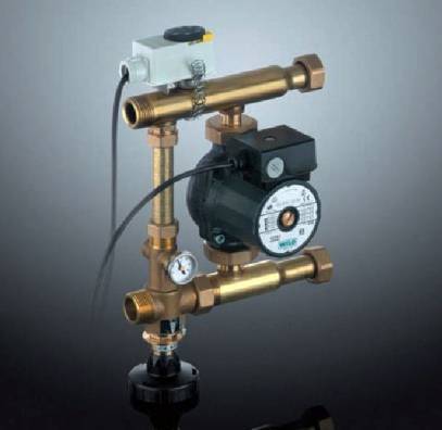
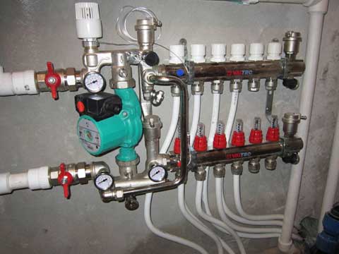
- Pump and mixing unit. It consists of a circulation pump, a three-way mixer, a temperature sensor, a pressure sensor. The equipment ensures the movement of the flow along the floor line, mixes the cooled liquid with hot water, which is supplied to the water circuit.
The pump-mixing unit may fail, therefore it is recommended to equip it separately and connect it to the manifold by means of a bypass. Shut-off valves are connected to the unit. They will allow you to shut off the water supply in order to be able to repair the equipment. In this case, the liquid will enter the line directly.
How to install correctly
The installation of the collector is carried out depending on the location of the main pipes of the boiler, as well as on the configuration of the pipelines for each individual room. As a rule, the point of installation is chosen a point equidistant from each final branch of the pipeline to the longest ones.
If it is supposed to heat a sufficiently large number of adjacent rooms, then it is more expedient to foresee in advance the presence and location of several units for separating the coolant. Compliance with this condition will provide an optimal hydraulic mode for the functioning of the entire system as a whole.
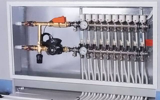
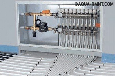
Manifold cabinet
Most often, collectors with two outputs are used, but in some cases it is required to install mixing units for four or more, up to twelve units. In this case, the entire structure is large enough, so it is very often "hidden" in a collector cabinet, which is specially equipped for this with their own hands. It is a metal box in which the collector itself and all its components are placed (pump, mixing units, loop outlets, etc.)
It can be closed or open. Also both built-in and hinged. The first ones have a front side decorated to match the overall interior. And the latter, in most cases, have a printed powder coating.
The dimensions of the cabinet directly depend on the size of the collector, taking into account all additional elements. The optimum mounting height is about half a meter from the floor. It is not entirely rational to fix the cabinet below, since later it will not be very convenient to insert the pipes into the collector itself.
In addition to functional advantages, such an installation will add aesthetics to the interior of the room, and will subsequently protect a rather expensive installation from accidental and unwanted mechanical damage.
Basement
When it is planned to use the collector simultaneously on two floors of a house in which there is a basement, then most often it is he who is determined by the location of the comb.
Device and principle of operation
In the process of laying out the pipes of the heating circuits, their ends from all rooms converge in one place, where the underfloor heating comb is connected to them. It is a distribution and mixing unit, whose task is:
- reduce the temperature of the heating medium coming from the boiler. To supply to the floor system, water is needed with a temperature of no more than 45 ° C, and the heat generator rarely heats the coolant to such a low threshold.Usually at the entrance to the comb the minimum is 55 ° С;
- provide the required amount of heat for each room. Here the distributor comb works as a regulator of the heat energy release, controlling the flow rate of the heat carrier in each circuit.
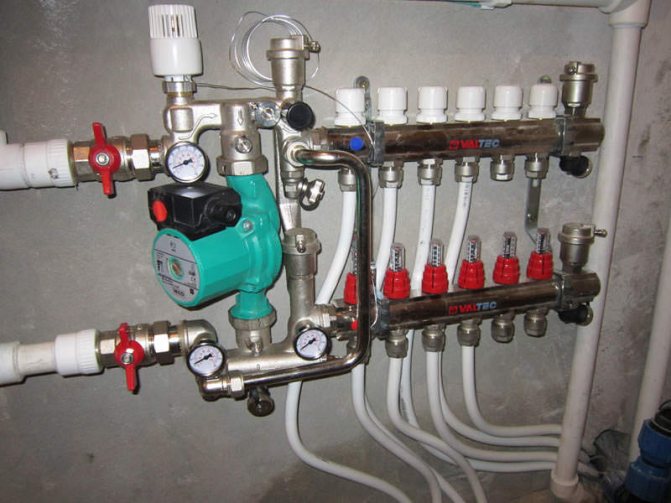
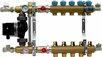
The distributor for underfloor heating visually resembles large heating combs installed in heating points. It also has 2 horizontal collectors - supply and return, to which consumers are connected, in our case - heating circuits. From the ends, the coolant is supplied to the collector pipes from the main line - from the boiler room. A typical comb connection diagram is shown in the figure:
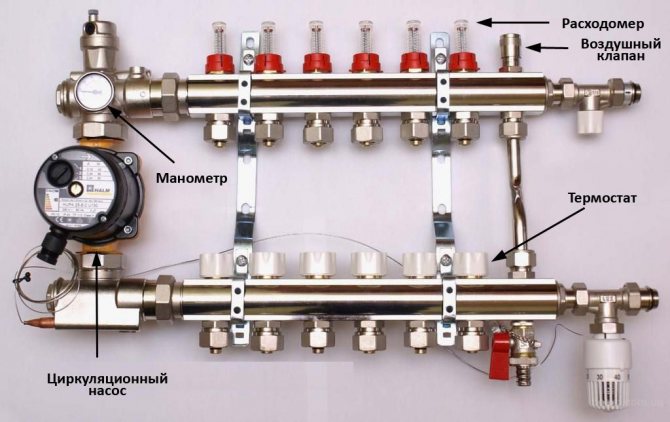
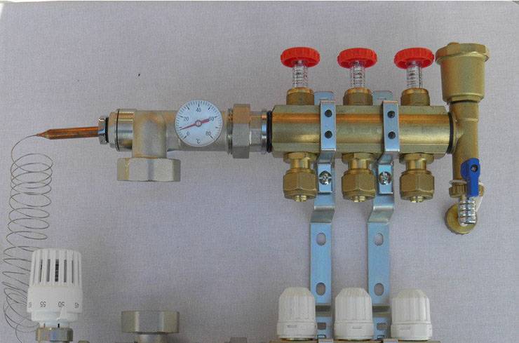
To regulate the amount of water leaving in each of the circuits, valves with a pressure rod are installed on one of the collectors. The adjustment can be done both manually and using various automation tools, for example, servo drives. To control the amount of coolant, the outlets from the second collector are equipped with flow meter flasks. The comb device is shown in detail in the diagram:
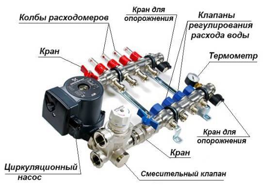
It can be seen here that in addition to the elements listed above, the circulation pump is an important part of the manifold. Without it, not a single circuit will be able to work, since it is the pump installed between the two collectors that is responsible for the circulation of the coolant through the pipes
The very principle of operation of the comb is as follows. Hot water from the boiler enters all circuits in the required amount, prompted to move by the pump. Moreover, the coolant moves in a circle until its temperature drops below the set one. Since the temperature of the water is controlled by the sensor of the three-way valve, after its decrease, the valve will begin to open the way for water from the boiler line, mixing it into the cooled coolant.
When the temperature in the manifold rises to the set limit, the three-way valve will close the line again. The pump of the comb of a warm water floor works non-stop, providing circulation inside the system, independent of other heating networks in the house. To empty the unit, the design of the comb provides for the installation of drain valves. In order to release air from this separate system, the circuit can be supplemented with automatic air vents.
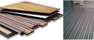
Comb: how it works
A comb for underfloor heating, which is a small piece of pipe, with numerous outlets provided on one end, greatly simplifies its installation. Such a collector practically organizes the activities of the entire system.
How the distribution manifold works

photo of a comb for a warm water floor
A comb for a warm floor consists of elements such as:
- Nourishing. Multi-way valves, two or three, operating in automatic mode, functionally serve to change the level of the coolant supply from the heating pipes.
- Thermal sensor. It is connected to the supply valve and, through its control element, marks the temperature of the liquid.
- Circulation pump. At the same time, it serves to form the flow rate of the coolant and mix the cooled liquid from the return manifold with the supplied one. As a result, the temperature drops to the maximum allowable - 55 ° Celsius.
- Control elements. They regulate the power of the coolant flow and provide a discharge in emergency situations when it exceeds the standardized. They are mounted on the inlet and outlet pipes of the comb.
How the system works

The heated coolant moves from the heating system towards the supply valve, where it mixes with the water that has cooled down. A thermostatic mixer for underfloor heating or a multi-way valve must be installed here, which, based on the temperature, regulates the position of the flap that distributes the hot liquid.
Advice
When using a valve, a thermal sensor must be installed. Having fixed the temperature, it will send the result to the control device.
A thermostat for a warm floor is more effective, since it simultaneously performs two functions related to temperature - it distributes and notes.
We can say that it is the thermostat that is responsible for the comfort temperature. More precisely, a thermostat, which can be purchased as a set or separately, sets and maintains a comfortable floor temperature. It is desirable that it be an electronic model operating in several modes.

Then, by a circulation pump, the liquid is pumped into the supply manifold. Since the tubes differ in length, the volume of the passing flow is different for them. Therefore, it becomes necessary to properly distribute this flow. For this purpose, the branch pipes are equipped with flow meters. They are screwed onto the thread on each loop of the return manifold.
On a note
In heating systems with forced circulation, a comb is used, the price of which is slightly more expensive compared to other models.
If servo drives are connected to the temperature sensors, then the temperature of the coolant in the pipeline is controlled automatically. It is enough for it to reach a given indicator, as the servo drive, having received a "message" from the control link, brings the rod forward, thereby reducing the volume of the coolant flow into the system.
Having passed all the way through the main pipes, the chilled water is collected in the outlet distribution manifold. The pressure is stabilized here by means of a special valve. When it reaches the highest x values, the stem opens and the excess part of the liquid is directed back or enters the supply pipe.
Installing the comb
Before choosing a collector, it is necessary to calculate the system. In particular, this concerns the diameter of the dies, which may differ from manufacturer to manufacturer. For example, the Luxor underfloor manifold can have different diameters of the inlet pipe. Some manufacturers' models, such as Icma, do not have safety groups, which include a bypass, a safety valve and an air vent. If necessary, they are purchased separately.
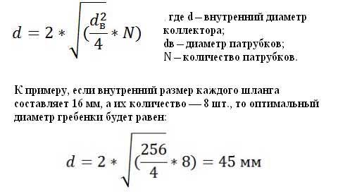
In order for the system to work correctly and the liquid is evenly distributed, the following condition must be met: the volume of the heat carrier passing through the manifold is equal to the total volume of liquid consumed by each circuit. Let's give an example of calculation:
What to do next if the water collector and thermostat are already correctly selected? Installation of a thermostat, as a rule, is carried out in each heated room away from drafts. Installing it is quite simple, and almost anyone can do it. As for the collector itself, the following recommendations are followed when installing it:
- The ridge must be placed at the highest point in relation to the laid heating main. This condition is mandatory, otherwise, in the event of an abnormal situation, it will be impossible to urgently remove excess air from the pipes.
- It must be located in such a place that when connecting the hoses, their maximum length relative to each other is the same.
- When calculating the number of inlet nozzles, they proceed from the area of the heated surface, while the comb, respectively, can be connected from two to twelve points.
- They are mounted in pairs: one feed, and the other - reverse.
- The comb is connected to the heating system at the last stage. Each pipe is equipped with a shut-off valve so that, if necessary, the room can be disconnected from the general circuit.
Collector placement rules
If we are talking about a private house consisting of several floors, collectors are placed on each of them.They will be responsible for heating the rooms on the floor on which they are installed. This helps to save on fuel costs. These devices make the circuit of each floor autonomous. If there are rooms on one of the floors that are not used during the daytime, their temperature can be temporarily reduced.
However, the temperature regime can be adjusted not only on the floor as a whole. Sometimes it is enough to turn off only one room or even just one radiator. This procedure will not affect the operation of all other heating devices in any way. In addition, heating of each of the radiators occurs evenly, since it receives the coolant through a separate pipe that fits exactly to it.
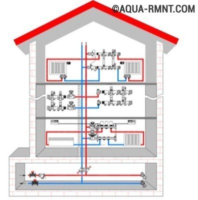
If the heating scheme is drawn up for a multi-storey building, you should place your own collector on each floor, then it will be responsible for the operation of heating devices on this particular floor.
Such a heat supply system may seem like a rather expensive structure, but in the process of operation, the benefits from its use become obvious. It pays for itself and the costs incurred at the installation stage will no longer seem excessive to you.
If there is a need for urgent repair of any of the circuits or any specific heating device, then the benefits of using a collector become obvious. The repairman will simply disconnect the damaged area or device from the coolant flow by turning off the valve at the outlet of the switchgear.
Of course, the use of this heating system has not only advantages but also disadvantages.
Of course, the pleasure of living in a warm place and being able to save on fuel and possible repairs is not cheap. But over time, all your upfront costs will pay off.
For instance:
- Significant costs at the installation stage. Plain pipes are cheaper than high strength steel products, which are required to make the manifold. This must be taken into account, and then add the cost of the locking mechanisms used in the circuit. With an increase in the number of circuits, costs also increase in direct proportion.
- The need for a circular pump. Such a pump is simply necessary for the operation of the beam system, and this entails an increase in energy costs.
- Additional expenses. If a separate branch is suitable for each of the heating devices, you will have to spend money on additional pipes and pay for their installation.
The increase in the volume of work will lead to the fact that they can be delayed for a long time. But during operation, this system will be more reliable and more efficient.
Comb installation rules
The place for placing the collector block must be determined at the design stage of the house. As mentioned above, if it is a multi-storey cottage, then such nodes should be provided on each of the floors. It is best to prepare special niches for them, which are located above the floor level.
However, if it was not possible to find a place for the node in advance, you can install this unit in any room in which it will not interfere with anyone: in the storeroom, in the corridor or in the boiler room. If only there was no excess moisture in this place.
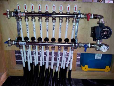
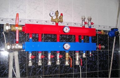
To keep the unit out of sight, you can place it in a special cabinet, which manufacturers of locking mechanisms offer their customers. The body of such a cabinet is made of metal. It is equipped with a door, and there are holes for heating pipes in its side walls. Sometimes the collector group is simply placed in a niche or on a wall, securing the combs with special clamps.
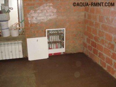
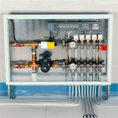
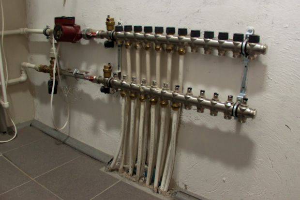
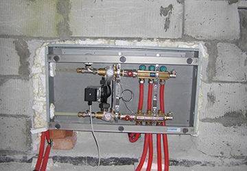
This comb is placed in a specially equipped place for it. As you can see, it looks quite aesthetically pleasing, and most importantly, access to this node will not be difficult.
The pipes that extend from this switchgear are located in the walls or in the floor, and then connected to the radiators.If the pipes are in the floor screed, the heaters should be equipped with an air vent or air tap.
The principle of operation of the distribution manifold for heating
In reality, it has a simple design, consisting of a small number of devices and assemblies. That is why it is deservedly very popular with buyers for installation in the heating system of individual housing construction.
Basic building blocks:
- Supply manifold;
- branch collector;
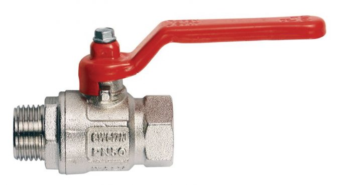
- ball control valve;
- shut-off and control valve;
- heating system make-up valve;
- heat carrier flow control valve;
- air vent.
The principle of the installation is quite simple:
- The coolant heated in the heating boiler enters the supply manifold.
- In which it is proportionally distributed between the supply pipes connected to the internal heating pipes and radiators in each heated room.
- After the hot coolant enters the heating devices, the process of heat transfer occurs through convection and radiation from hot water to the air in the room.
- The cooled heat carrier enters the return pipeline through which it follows to the return manifold-distributor and then again flows to the boiler unit for the next heating cycle.

Control elements
Setting up the underfloor heating collector is impossible without special devices. With their help, the optimal heating mode of the system is established, the flow of water in the pipelines is regulated. Each of them has a specific function.
- Water temperature sensor
Installed on the inlet and outlet pipes of the device. These devices do not affect the operation of the system, but indicate the current heating value. The difference in values can be useful in calculating work efficiency. They also serve as an indicator of a violation of the heating mode.
- Central thermostat with servo mechanism and sensor.
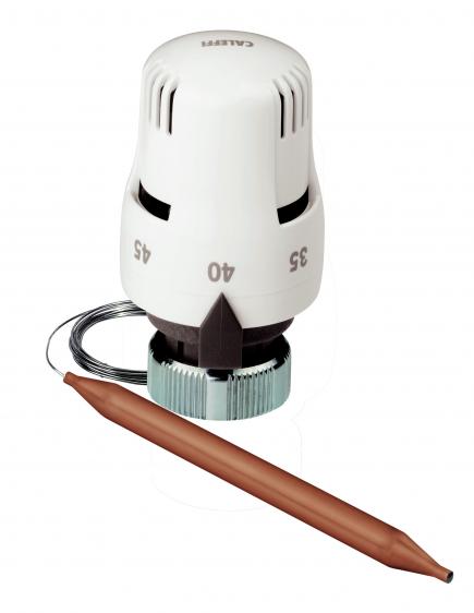
It is mounted on the inlet of the inlet manifold and connected to the return pipe with cooled heat carrier. The temperature sensor is housed in the comb body. There is a rotary knob on the thermostat body, with which the required temperature level is set. From the sensor, the device receives readings about the degree of water heating. Depending on this, the flows of cold and hot heat carrier are regulated.
- Servos on the inlet manifold nozzles
By the principle of operation, they are completely similar to the thermostat, but with minor additions. With their help, the volume of water flow is regulated for each circuit of the water floor. This can be done manually or automatically, depending on the model. For the latter, servo drives with built-in temperature sensors are used, which can be connected to a common remote thermostat.
- Flow meters
Devices not necessary for installation, which, however, can become effective elements for manual control of the operation of a water heated floor. They are installed on the return manifold pipes and are shut-off mechanisms with a glass bulb.
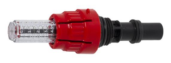
When the head is turned on the body, the stem in the device changes its position. This affects the volume of fluid passing through it. For clarity, a measurement scale is applied to the surface of the flowmeter, which indicates the flow rate of water l / min.
Comb for water floor heating principle of operation
- normalize water temperature;
- distribute liquid along the contours.
Laying underfloor heating pipes installation how to choose a step and make a less costly circuit
In heating boilers, the liquid heats up to 60 - 90 ° C and hot diverges along the circuit.
For obvious reasons, it is impossible to pass such a hot coolant into a warm floor.
Lowering the temperature is one of the main tasks implemented in the manifold assembly. The temperature can be lowered in two ways:
- By mixing.
- Limitation.
Mixing a cooled coolant with a hot one is the most popular method. Mixing takes place in the three-way valve. After the liquid is circulated by the circulation pump along the circuit, it cools down. It is this cooled return line that is added to the hot coolant. The proportions of both flows are verified by the thermal head. Its working part is installed on the valve itself, and the sensor is installed on the supply.
Instead of a thermal head, there can be a servo drive. And for stable heating systems, when the boiler produces a relatively equal temperature, you can set the three-way one in one position, attach a thermometer to it and control the degrees in manual mode.

The main elements of the manifold assembly
Without a circulation pump, a water floor circuit will not work. Also, if you place the pump up to a three-way valve, the coolant will not enter the floor coil, but will go in a small circle, where the resistance is less.
Temperature limitation is realized by installing a special thermal head into the system, which measures the temperature of the coolant. Outwardly, it looks like a radiator thermostat, but is fundamentally different from the latter, which measures the air temperature in a room.
A person sets a comfortable indicator for himself, and the device, fixing the excess of the threshold, limits the clearance inside the device, reducing the flow of the coolant.
Comb selection criteria
The first step is to pay attention to what material this structure is made of. The most popular collectors are made of brass, which are produced by casting
In this case, a strong and durable part is obtained, but at the same time it is very expensive.
Welded products made of stainless steel are cheaper. The comb turns out to be quite strong, but this material can be susceptible to electrochemical corrosion.
Products made of high-quality plastic material are considered a budget option. In terms of their qualities, they are not inferior to metal parts.
The next criterion for choosing a collector is the number of production branches. It is best to choose a product with taps equal to the number of heated circuits so that you do not have to drown out unnecessary holes.
Further, the technical equipment of the collector is taken into account for automating and regulating the temperature of the coolant. If you need a comb that will serve you for a long time, then brass is your option.
If you need a comb that will serve you for a long time, then brass is your option.
Today there are combs that can be connected to thermostats and programmable controllers. With their help, it is much easier to carry out adjustment, as well as to control the quantity and quality of the coolant in the circuits.
How to build a collector yourself
You can buy a ready-made uze, choosing one that would approximately meet the needs of your home. But it is quite difficult to achieve an exact match. Therefore, it is better to make a heating comb with your own hands. Let's figure out what is needed for this.
Planning phase
There are a number of parameters of the heating system of a house that you should know when building a block.
- The number of circuits through which the heated water will pass.
- The number and technical characteristics of the heating equipment included in the scheme.
- Additional equipment involved in the installation. This refers to pressure gauges, thermometers, taps, storage tanks, valves, pumps, etc.
It is also necessary to provide for the possibility of increasing the load, if over time it is necessary to build in elements that were not taken into account in advance. This can be, for example, solar panels or a heat pump.
It is necessary to foresee in advance not only the number of circuits operating in the heating system, but also additional equipment that will be included in the general scheme
Determining the block structure
The design of the future node depends on the connection point of each of the circuits. After all, there are some connection nuances that cannot be ignored.
- Boilers (electric and gas) must be connected to the top or bottom of the comb.
- The circulation pump should be connected from the end of the structure.
- Solid fuel units and indirect heating boilers also need to be cut from the end.
- The supply circuits of the heating system are connected from below or from above.
For clarity, it is necessary to make a drawing of the future compact and neat unit. This will help determine the amount and types of materials that we need. All the necessary dimensions, threaded connections with a thread pitch are applied to the drawing. All contours should be marked in order to be guided by the drawing when connecting.
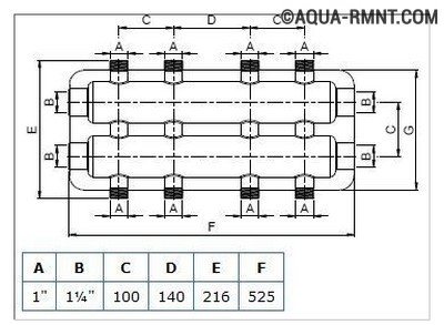
This drawing shows a four-way manifold. You can skip the drawing and limit yourself to a sketch, but do not forget to put all the dimensions necessary for work on it.
The distance between the nozzles of both combs should be between 10 and 20 cm. These are optimal parameters for service. The distance between the feed and return combs themselves should be within the same limits.
Sequence of work
For the manufacture of both dies, not only round but also square pipes can be used. The sequence of work performed is as follows:
- In full accordance with the parameters indicated in the drawing, we purchase all the necessary materials.
- According to the drawing, we make a connection by welding pipes, taking into account their subsequent functions. Welding points should be cleaned with a wire brush and degreased.
- Testing a homemade node is a necessary stage of work. To do this, all pipes are hermetically closed except for one through which hot water is poured into the system. Let's take a good look at all the joints: they shouldn't leak.
- The collector can now be painted and dried thoroughly.
- Next, pipes, locking mechanisms and control equipment should be connected to it.
After that, the device is ready for use.
This one will differ favorably from purchased products in that it was built taking into account the needs of a particular house, and this is very important for its further operation. Of course, a high-quality and functional device can only be obtained if the master knows how to handle a welding machine and a locksmith's tool.

In order for a homemade manifold block to work more efficiently than a purchased one, the craftsman needs to be able to handle both welding equipment and locksmith tools
You can learn how to make a polypropylene manifold by watching this video:
Heating of premises by means of water-heated floors is considered one of the most effective ways in terms of saving energy resources and even distribution of heat. As you know, heating is carried out by means of pipes with a heat carrier laid in the screed. Each room is a separate closed loop, or even several. Their work is controlled by one common unit - a comb for a warm floor. Information on how this unit functions, the nuances of its assembly and regulation is offered to your attention in this article.
Working with collector flow meters
Hydraulic balancing of underfloor heating loops consists in regulating the flow rate in each coil. Depending on the length, a different amount of the incoming heat carrier may be required in order for it to cool down exactly to the calculated value when passing through the loop.The quantitatively required flow is determined as the ratio of the heat load on the loop to the product of the heat capacity of water or other heat carrier by the temperature difference in the supply and return: G = Q / s * (t1 - t2).
You can often find recommendations to determine the flow rate of the coolant according to the performance of the circulation pump, that is, to divide its supply in proportion to the ratio of the loop lengths. Such advice should be avoided: besides the fact that the length of each coil is quite difficult to calculate, one of the most important rules is violated - to choose equipment parameters based on the needs of the system, and not vice versa. Attempts to distribute the flow rate in the described manner almost always lead to the fact that the flow in the loops differs significantly from the calculated values, which makes further adjustment of the system impossible.
The very same adjustment of the flow with flow meters is quite simple. In some models, the throughput is changed by turning the body, in others - by rotating the stem with a special key. The scale on the body of the flow meter indicates the flow rate in liters per minute, you just need to set the appropriate position of the float.
Almost always, when the throughput of one flow meter changes, the flow rate in the remaining loops changes, therefore, the adjustment is carried out several times, sequentially calibrating each branch. If such changes are especially pronounced, this indicates a lack of throughput of the control valve through which the collector is connected, or about too low performance of the circulation pump.
Device
A comb for a water heated floor consists of two horizontal pipes - supply and return, with outlets for connecting floor branches. The coolant is supplied from the ends.
There are valves on one pipe to adjust the amount of fluid entering the loops. The comb adjustment is possible manual and automatic, using servo drives. To control the volume of the coolant, there are flow meter flasks at the outlets of the second collector.
A comb for underfloor heating is:
- supply and discharge pipe;
- shut-off valve at the inlet and outlet;
- fasteners for assembly;
- thermostat;
- faucet for draining the coolant;
- air bleed valve;
- valve for supplying water from a source;
- mixing unit;
- pump.
The collector is fastened to the wall using metal brackets.
Installation of a comb in the heating system and its calculation
Comb in the underfloor heating system
The installation location of the distribution manifold in the heating system depends on its purpose. Most often it is used to organize multi-circuit heat supply. However, in addition to this, it is an indispensable element of a water-heated floor.
Before proceeding with the installation, you should calculate the heating manifold. The main task of this process is to evenly distribute the pressure across the heating circuits. If the system is a complex circuit of highways, it is recommended to make a calculation using special programs. For a simple system with up to 5 contours, the principle of equal sections can be applied.
N0 = N1 + N2 + N3 + N4
Where N0 is the diameter of the collector, N1, N2, N3, N4 are the cross-sections of its outlet pipes.
The same calculation scheme is used when making a do-it-yourself heating comb.
It is important that the dimensions of the inlet and outlet headers match. It is noteworthy that the standard device of the heating comb has no requirements for its shape.
Those. it can be either round or square. The basic principles of installing collector heating are as follows:
- To improve circulation, it is recommended to install pumps for each circuit. At the same time, the distribution manifold of the heating system should not provide synchronization of the pumps;
- If the unit is located in a boiler room, the installation of a protective box is optional. The exception is the installation of a polypropylene heating comb in the underfloor heating system;
- To adjust the volume of the coolant, it is necessary to install control valves on each inlet and outlet pipes - inlet valves and balancing flowmeters;
- When planning the installation of a heating manifold, it is necessary to provide for the presence of a safety group on the distribution unit.
An example of a heating manifold installation diagram
It should be remembered that these are only general recommendations that can be changed and supplemented depending on the specific parameters of the heating system.
In addition to these rules, experts advise taking into account the difference in the length of the circuits when calculating the heating comb. It is recommended to draw up the scheme so that their length is approximately equal.
To reduce energy consumption, a mixing unit can be installed in the heating comb device, which, in turn, will reduce heating costs.
The role of the collector
In the boiler, the coolant is heated to a temperature of 80-90 ° C. This is normal for radiator heating, but too high for underfloor heating. All the elements that make up the line will withstand high loads. The water will heat the floor surface to a high temperature. It will be impossible to walk on it.
The maximum heating of the floor surface is no more than 30 ° C, the optimum is 22 ° C. The coolant must be brought to normal temperature. This function is taken over by the comb for the warm floor.
Plastic pipes are used for the water floor. The working temperature of pipes is 65 ° C, they can withstand high thermal conditions for a short time. To keep the line intact, it is connected to a manifold. A contour of metal pipes is removed from it. They are connected to the outlets in the firebox.
The comb for underfloor heating has a distribution function. It separates the hot and cold fluid flow: it has outlets for the supply pipe and "return". The collector circuit provides for the connection of 2-3 circuits for the simultaneous heating of several rooms.
A control unit and a three-way valve are installed on the distribution unit. These devices are necessary in order to control and regulate the temperature of the liquid in the underfloor heating circuit.
Servos play the role of the thermostat. They are installed on each circuit. This allows you to regulate different thermal conditions of the floor in individual rooms, control a certain amount of water in heating systems in small and large rooms.
We recommend: How to turn on the warm floor?
Features of product installation
When installing this design, it is necessary to take into account a number of rules and features. Typically, the collector is installed on a wall, in the middle or closer to the floor. For this, it is best to use a special manifold cabinet, which gives a more aesthetic appearance to the structural unit.
Holes must be drilled in it for suitable piping. The comb is attached so that it is possible to bleed air from the heating circuits. This will allow you to easily carry out repairs in the event of an accident.
The length of the contours should be approximately the same to make it easier to adjust. This is done according to two indicators: the flow rate of the coolant and its temperature. For this, a flow meter and temperature sensors are built into the circuit.
An important condition when installing underfloor heating is that the total length of each circuit should not exceed 60 m.Otherwise, it will be difficult for the coolant to overcome the hydraulic resistance in the pipelines
When creating a warm floor, a separate heating branch is laid in each room.
This is due to the fact that there are restrictions on the length of one branch, as well as ease of installation.
The distribution of the coolant from a single boiler flow to each branch takes place in a special unit called a collector, or a comb for a warm floor.
With your own hands, you can make an analogue of a factory collector, which will perform its functions no worse, but for less money. What you need to buy, how to properly assemble and assemble in practice.
How to choose and install?
The main factor is the number of connected circuits. It is recommended to choose a model with 1 circuit more. Perhaps in the future it will be necessary to increase the heating area, which will require one more connection. You can buy ready-made models with fittings for connecting pipes, built-in taps, thermostats.
Collector-comb for 3 outlets.
Other selection options:
- Calculation. The cross-section of the collector must be equal to the sum of the area of the inlet pipes.
- Material. The most durable and expensive ones are made of stainless steel. The more common option is brass. Polypropylene products are cheap, but designed to operate in low temperature heating systems that are sensitive to pressure drops.
- Manufacturer. It is recommended to buy fully assembled models from the manufacturers Rehau, Kermi, Valliant, Valtec, FIV, Rossini.
It is possible to assemble the comb yourself. But then you need to correctly calculate the power of the circulation pump, the dependence of the flow rate of the coolant on the diameter of the collector.
Installation of a comb for underfloor heating begins with choosing an installation site. It is recommended to make lines of approximately the same length, the length of each should not exceed 60 m. Free access to the distribution block is taken into account for the possibility of inspection, maintenance or repair.
First, the combs are installed, then the mixing unit is connected. This must be done before pouring the underfloor heating so that there is free access to the pipes. Connecting highways to the manifold pipes, checking the operation of the system. It is recommended to make a pressure test; after starting the heating, the absence of leaks is checked. At the same stage, the comb operation is regulated.
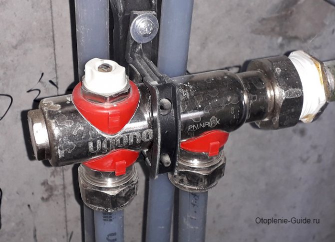
Two-way valve design
In the installation scheme for underfloor heating, the valve is installed directly in front of the comb. It is connected to a temperature sensor, which is located at the return manifold of the coolant. In addition, the distribution unit diagram includes:
- circulation pump;
- balancing valve;
- check valve.
The check valve is part of the manifold
At the beginning of the heating process, the device is in an open state, and the heat carrier enters the collector. The valve remains open until the water temperature reaches the operating value. As soon as this happens, the tandem "sensor + thermal head" will close it, and the coolant will stop flowing from the heating boiler.
During this period, the underfloor heating comb pump will independently circulate hot water through the heating circuits. In this case, the coolant will gradually cool down, and when its temperature drops below the operating temperature, the valve will open again.
Correct mixing of hot and chilled water occurs due to a balancing valve that regulates the volume of the waste heat carrier.
Purpose of the device
The design of the comb for warm floors resembles heat collectors, which are installed together with a hydraulic arrow. Place the comb at the collection point of the ends of the heating pipelines after they have been laid on the floor surface. Its direct purpose is:
- Providing the required amount of coolant for heated rooms. This is achieved by regulating the flow using special valves.
- Reducing the water temperature to operating parameters, which should not exceed + 45 ° C.
The main part of the collector is made up of two parallel pipes for direct and reverse supply of the heating medium.On them there are nozzles, to which the ends of the heating pipelines are connected. When installing the underfloor heating comb, the two main collectors are connected to the corresponding pipelines of the heating system.
In this video you will learn about the types and main differences of the comb:
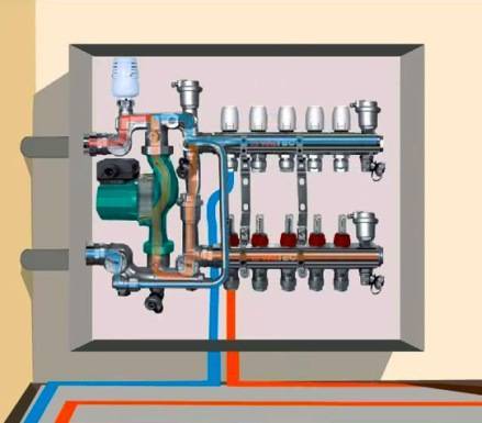
How the collector works
Water floors are laid in various ways, for example, concrete or floor, but regardless of the technology chosen, it is necessary to purchase and install a manifold cabinet.
Note The collector box is recommended to be installed on the wall as close to the middle as possible and most often at the very floor.
In the future, two pipes will be installed into it:
- supply, which leaves the boiler and supplies a hot coolant to the system;
- returnable, which performs an absolutely opposite role: it serves to collect water that has already been used up and has had time to cool down. It is returned back to the boiler and the process is repeated again.
The cyclicity of the process is provided by another built-in component of the system - a circulation pump. One way or another, during the operation of a warm floor, say, during repair work, the system has to be turned off. For this, each of the pipes is equipped with shut-off valves. A plastic pipe and a metal shut-off valve are connected to each other through a compression fitting. Then a comb is connected to the valve, mounting an air vent on one end, and a drain valve on the other. After assembling the cabinet, proceed directly to the installation. And only with the comb installed on the wall can the pipes of the contour be cut along the length.
Note To ensure the tightness of the connection, the pipes are cut strictly at right angles.
How to build a collector yourself
You can buy a ready-made uze, choosing one that would approximately meet the needs of your home. But it is quite difficult to achieve an exact match. Therefore, it is better to make a heating comb with your own hands. Let's figure out what is needed for this.
Planning phase
There are a number of parameters of the heating system of a house that you should know when building a block.
- The number of circuits through which the heated water will pass.
- The number and technical characteristics of the heating equipment included in the scheme.
- Additional equipment involved in the installation. This refers to pressure gauges, thermometers, taps, storage tanks, valves, pumps, etc.
It is also necessary to provide for the possibility of increasing the load, if over time it is necessary to build in elements that were not taken into account in advance. This can be, for example, solar panels or a heat pump.

It is necessary to foresee in advance not only the number of circuits operating in the heating system, but also additional equipment that will be included in the general scheme
Determining the construction of the block
The design of the future node depends on the connection point of each of the circuits. After all, there are some connection nuances that cannot be ignored.
- Boilers (electric and gas) must be connected to the top or bottom of the comb.
- The circulation pump should be connected from the end of the structure.
- Solid fuel units and indirect heating boilers also need to be cut from the end.
- The supply circuits of the heating system are connected from below or from above.
For clarity, it is necessary to make a drawing of the future compact and neat unit. This will help determine the amount and types of materials that we need. All the necessary dimensions, threaded connections with a thread pitch are applied to the drawing. All contours should be marked in order to be guided by the drawing when connecting.

This drawing shows a four-way manifold. You can skip the drawing and limit yourself to a sketch, but do not forget to put all the dimensions necessary for work on it.
The distance between the nozzles of both combs should be between 10 and 20 cm. These are optimal parameters for service.The distance between the feed and return combs themselves should be within the same limits.
Distribution manifold connection rules
The selection of a site for the location of the collector must be based on the principle of equidistant location of equipment from it. If this requirement is neglected, then a high pressure arises at the more extended nodes of the system, which will negatively affect this section. Therefore, the allowed difference in the lengths of pipe sections from the comb to the batteries should not violate the 1: 2 ratio.
Or, in other words, the length of pipelines from the first radiator to the collector and subsequent batteries cannot be less than 2 times. If the above characteristics are exceeded, it will not be possible to ensure the exact operation of the comb. In the case when the house has many floors, then the collector is installed on each of them. There are a number of methods for positioning the manifold in the heating system: in a special enclosure or directly on the wall.
When installing the collector on the walls, specialized niches are made in them. To install the heating comb, a place is determined above the floor level. In terms of dimensions, the niche must correspond to the dimensions of the comb, taking into account attachments and piping of heating pipelines. The area where the collector is located must certainly be dry. Usually, for these purposes, a corridor or an auxiliary room is chosen, where the distribution system will not interfere with anyone.
In case the distributor is located in the passage, it is recommended to place a special metal cabinet with a door and openings for the input / output of pipelines in the niche. This design, as a rule, is completed with special fasteners to secure it securely.