0
18541
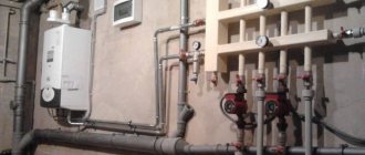
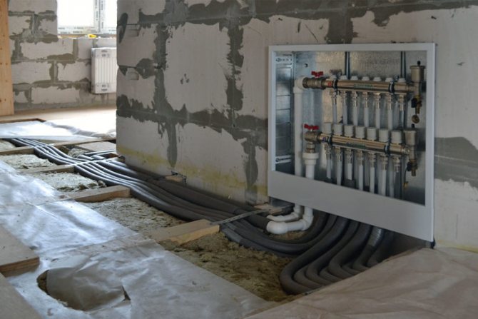
The installation of the water floor covering starts from the walls, where the place for the collector is prepared. First of all, a recess is made in the surface of the wall, where it is planned to place the collector cabinet for the device. It creates a convenient system connection and practicality of use. It is often installed in boiler rooms or rooms where the heated floor itself is located.
general information
Almost every heating system cannot be imagined without a heating distribution cabinet. Its installation solves several problems at once.
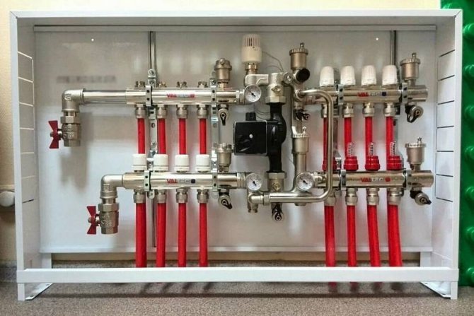
Compared to the do-it-yourself piping, the manifold wiring is much more efficient and practical, and it looks very aesthetically pleasing in a special cabinet. The manifold cabinet for heating can accommodate both a meter and electrical equipment.
Here are some points to prove that the switch cabinet is indispensable:
- in it you can hide the collector itself from the eyes;
- there the connection of the underfloor heating system pipes with the entire heat supply system is carried out;
- this is a place for mounting other connections and measuring instruments.
A manifold cabinet for a warm floor is designed to hide and protect expensive engineering units from interference from the outside.
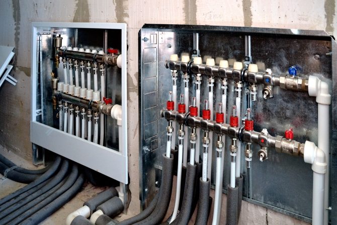
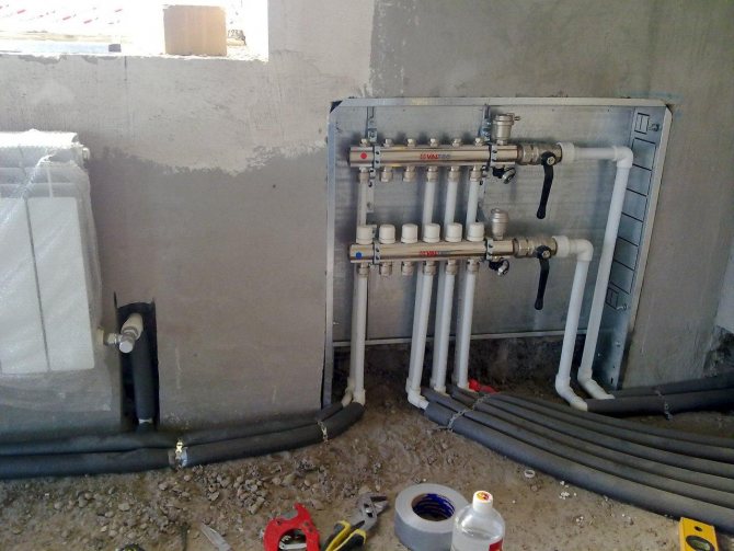
Manifold cabinet mounted
System elements
After connecting the cabinet, the supply and return pipes are mounted. Hot water flows from the boiler along the supply circuit. The liquid cooled down during heating flows back to the heating source.
The circulation of the coolant is due to the pump. A shut-off valve is installed in the cabinet on each pipeline. If necessary, remove several elements from the system (during repair work or if you want to save money), this does not affect heating in the rest of the house. You just need to turn off two taps.
Compression fittings will help if you need to join a plastic pipe and a metal valve.
The main components of the cabinet:
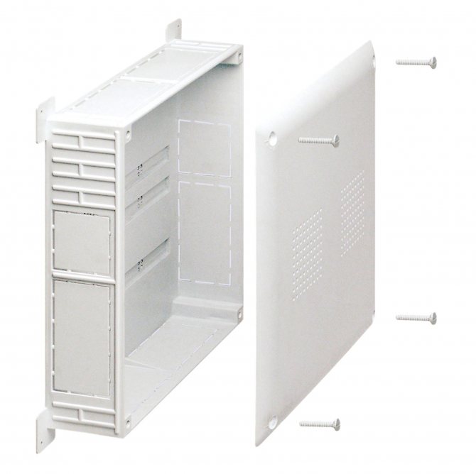
- The body is a box that consists of stainless steel or durable plastic.
- Fastening system (depends on how the structure will be located, on the surface or in the middle of the wall).
- Often spacers or anchors are used as fasteners. Some cabinets have brackets and adjustable clamps.
- The door is its function in protecting the content from unnecessary external interference. It is fastened with hinges, has a lock or a latch. Popular design colors are white, beige, less often other shades.
The manifold cabinet is not difficult to do with your own hands. However, it is not so expensive in specialized stores to waste time on its creation.
You can find out more about the collector for underfloor heating here.
What are collector systems for underfloor heating
The underfloor heating system consists of many circuits - pipes through which the coolant flows. At the same time, its temperature rarely exceeds 35-40 degrees Celsius. Technically, only condensing gas boilers are capable of operating in this mode. But for collector warm floors, such boilers are rarely used.

A standard boiler heats the heating medium to 70–90 degrees Celsius. Such a high temperature is not suitable for underfloor heating. In order for a coolant of a suitable temperature to enter this system, a collector is used. The principle of its operation is simple: in the collector, two water flows are mixed - the cooled return flow and the hot one from the feed coming from the boiler.As a result, the required level of the coolant temperature is achieved.
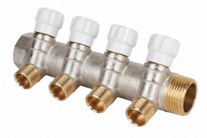
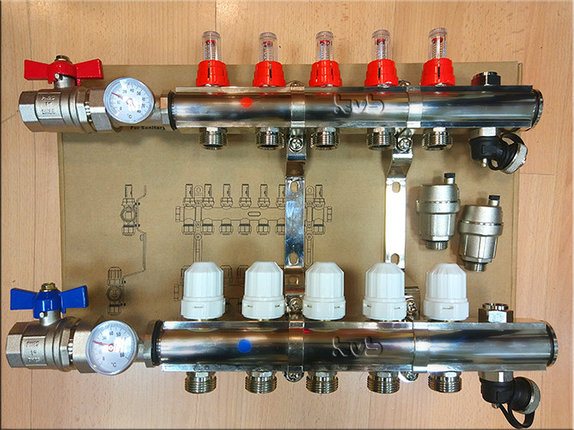
To create the same temperature for all underfloor heating circuits, first, the coolant enters the collector comb. The main part of the cooled water is pumped into the heating boiler, but a certain amount of return flow is fed into the mixing system and serves to cool the heat carrier heated in the boiler. In fact, these devices (return and supply combs) are called the underfloor heating collector. The combs are not always equipped with a mixing unit.
An ideal collector floor system consists of equal length circuits, and the collector receives water of the same degree of heating. This is how a certain balance and equilibrium of the temperature of the coolant in the system is achieved. But such a wiring option is practically not found, because the rooms in apartments and houses are different in geometry and area, and therefore, the length of the pipeline in the underfloor heating system will not be the same. Accordingly, in longer sections, heat loss increases and the return temperature will be lower.
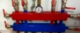
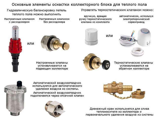
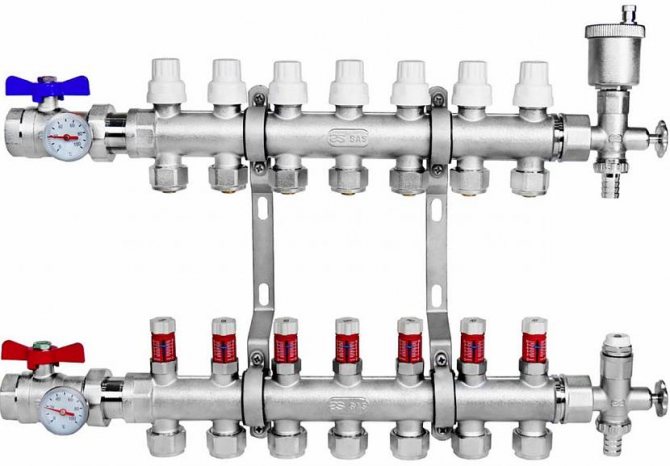
The temperature difference between the flows is compensated for by installing flow meters on the supply manifold, and special valves on the return manifold, which allow adjusting the flow rate of the coolant. Flow meters are a device that informs about the speed of water movement in the pipeline. A special float is installed in a plastic transparent body, which allows determining the flow rate of the coolant on a graduated scale.

The principle of temperature control is simple: the higher the flow rate, the more heat can be given off by the circuit through which the fluid moves. Conversely, if you want the temperature of the collector underfloor heating to be lower, close the control valve, thereby reducing the flow rate and heat transfer of the floor.
The flow rate is changed by turning the valve knob, each circuit can be adjusted individually. When installing a collector underfloor heating, it is best to sign the adjustment valves and circuits, and also apply them to the diagram so that in the future you do not have to look for the correspondence between the valve and the circuit.
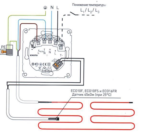
Manual adjustment is not always convenient. Today, automatic devices are used in collector floor heating systems. Special servos are installed on the valves, which receive a command to close or open the flow from the thermostats installed in each room. If the room temperature is lower than the set one, the thermostat sends a signal for a larger valve opening, and vice versa.
Advantages of a distribution cabinet
A manifold cabinet for heating is a practical and necessary thing for the following reasons:
- Its use makes it possible to reduce the number of pipes required to connect a warm floor. The pipes do not need to be pulled from the heater, as the collector can be placed in the same room.
- In addition to the collector mounting, the cabinet can also be for water supply, a liquid meter is installed in it.
- When repairing and modernizing the heating system, you can easily access the guide loop.
- Safety is one of the most important points. A door with a key will help protect the collector cabinet with expensive components from children.
Device
When the installation of a water-heated floor is carried out, the work may take a little time. Everything will depend on the length of the underfloor heating, the availability of appropriate equipment and materials, as well as skills.
A collector with a pump for underfloor heating refers to one of the components of the entire system to provide heat to the room. At the same time, it has a peculiar character of efficiency with its own nuances. The most basic of them is that the preparation of pipelines is carried out separately from the entire system.And this is despite the fact that the coolant circulates through all pipes at the same time.
The manifold is necessary in order to be able to isolate the supply and return pipes from the water heating system. The kit contains the following components without fail:
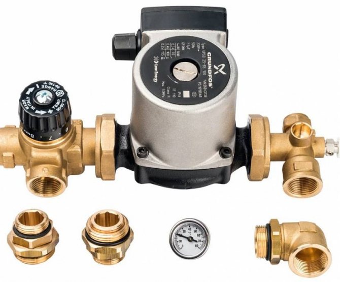
- Pumping group.
- Heating medium distributor.
- Cooled back water collector.
Nobody thinks about how much it costs to install a warm floor. It is best to purchase components in aggregate and from one manufacturer. This is the only way to get the highest quality. In addition, in this case, the cost will be less, regardless of the length of the underfloor heating circuit.
Cabinet types
There are two types of heating distribution cabinets:
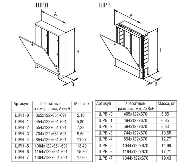
- Built-in manifold cabinet - installed in the wall itself or hidden under the plasterboard cladding. As a rule, such models have unpainted sides, because they contain outlet and fastening spans. Often the structure is 120 mm deep, 465 to 1900 mm wide, and about 650 mm high. To simplify the markings on the niche and to arrange collectors of different sizes in the cabinet, certain structures have retractable legs (they allow the cabinet to be raised up to 100 mm in height).
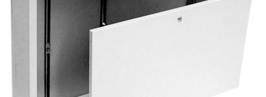
Recessed manifold cabinet - Outdoor models are easy to install and wall-mounted. The side walls of the structure are coated with a special anti-corrosion agent or powder paint. The outlet holes are first covered with easily removable metal strips. The external heating manifold cabinet is almost identical to the dimensions of the built-in structures. Legs are also present.
External metal collector cabinet Wester SHRN-5
It is the built-in distribution cabinets that are more in demand on the market, since they are not so noticeable to the eye, fit well into the interior of the premises and are practical in operation.


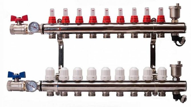
Collector components
The device of the underfloor heating system using a collector includes the following main components, which cannot be dispensed with:
- Collector supply to the floor. It can also be called a flow control valve for a single branch.
- Mixing unit, as well as a three-way valve.
- Servo-assisted regulation valve. This is the so-called return collector, which is almost identical in cost to the supply.
- A circulation pump with a drainage device.
- System automation group.
- Combs, but if necessary. They are more suitable for supplying heat to a room using radiators.

Automatic control valves allow you to interrupt the supply of heat carrier to the warm floor after reaching a certain temperature. It no longer enters the circuit until it cools down. It doesn't matter how much the warm floor consumes, since all indicators will decrease due to constant monitoring. They also use flow meters that allow setting the required parameters of the heat supplied to the room. Setting up is very easy and hassle-free. They are located on the back of the comb.
Both combs are connected to each other using a circulation pump. It allows water to constantly circulate through the underfloor heating system. It should be noted that each of the elements of the collector group is purchased both separately and in aggregate. In the latter case, you should not worry that something will not be enough and will not be available. But collecting the entire system on your own requires some knowledge. So, for example, it is worth knowing that you will have to purchase a drainage drain valve for the pumping group. In addition, it will be necessary to install the manifold cabinet itself before starting all work, which is additionally equipped with a point for venting air from the system.
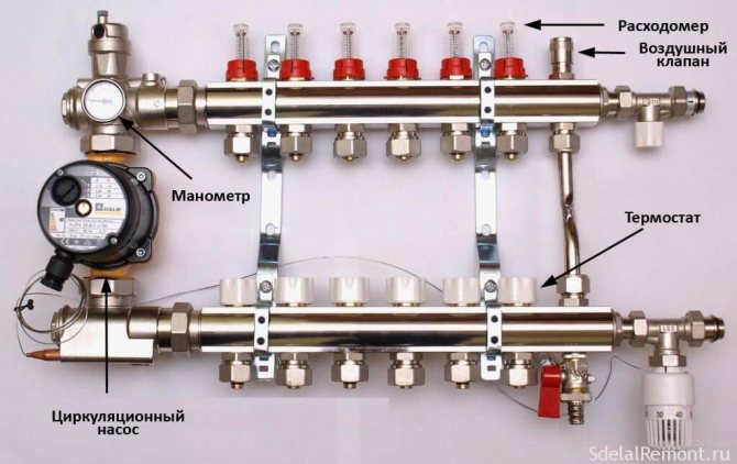
The comb system is equipped with various measuring and indicating instruments. This includes pressure gauges, thermometers, heating sensors, and more. The latter, by the way, are installed in the floor screed. What kind of floor filling option to choose should be guided by the requirements of the underfloor heating system itself, its features.
The quality of the device of the collector group for a warm floor will subsequently affect the performance of the heating system. In addition, the reliability of a water-heated floor is based on all its components. Careful attention during installation will allow you to get the desired result that can last for a long time.

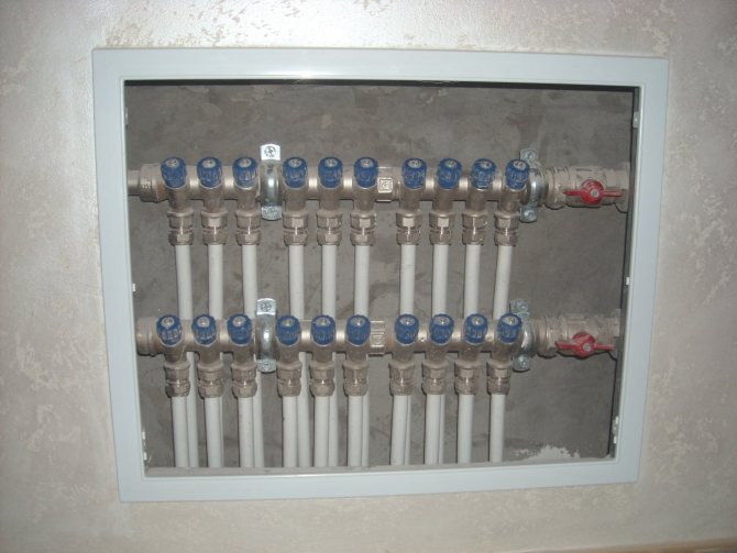
Cabinet Installation Recommendations
The collector is placed in a box, the structure is attached to the wall in a recess. In the middle there are vertical strips that fit the width of the main unit. On it, the circuits and other elements of the thermal supply of rooms are connected, and other elements are installed.
The underfloor heating collector cabinet is connected taking into account the increase in the floor by the point of the thickness of its layers.
After fixing it, a hot coolant and a return circuit are carried out. The supply pipe is for warm liquid coming from the heating boiler, the return pipe is for cold one.

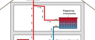
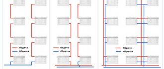
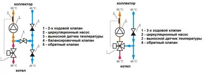
Underfloor heating collector circuit: 2 options
The simplest connection diagram for a warm collector floor is straightforward. It implies that a minimum of nodes are placed between the boiler and the manifolds in the form of a pair of valves and a pump that provides forced circulation of the coolant in the system. Let's be honest, this scheme of a warm collector floor is simple, but not the most successful, many already during the first year of operation convert it to an adjustable one.

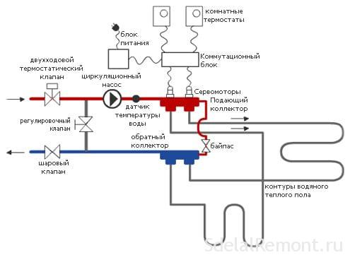
The operation of a controlled system is most often based on the use of a two-way and three-way valve. If, in addition to the underfloor heating, there are also heating radiators in the scheme, then a circulation pump is definitely needed, since the pump with which the heating boiler is equipped will clearly not be enough to provide a full flow of coolant in the heating system. Typically, a pump built into the boiler serves to pump the coolant through the radiator system, and the second pump is installed on warm floors. The whole structure is called a pumping and mixing unit.
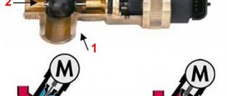
Three-way valve circuit
The three-way valve is used to mix the hot coolant from the boiler and the cooled liquid that came back from the heating system.
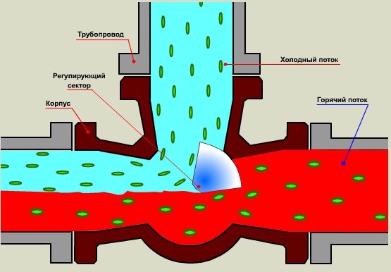
A special sector is installed inside such a valve, which allows, depending on the data coming from the temperature sensor, to regulate the return flow. Thermal sensors control the operation of the sector and the valve autonomously. But regulation by means of a thermostat is also possible - manual or electronic.
The circuit using a three-way valve is fairly simple. The valve outlets are connected to the hot water supply line and the pipeline with the cooled liquid, the third outlet goes to the supply manifold of the collector warm floor. The pump is installed after the three-way valve, while it is important that the pump pumps the coolant towards the supply manifold. After the pump, a temperature sensor is mounted, connected to the liquid flow regulator (sector) in the three-way valve itself.
Principle of operation:
- A hot heat carrier is supplied from the boiler. In this case, the valve completely passes this liquid without adding a cold heat carrier.
- Immediately, the valve receives a signal from the temperature sensor that the liquid is too hot and does not correspond to the set temperature value, the valve opens to mix the cooled heat carrier.
- The process of mixing heat carriers of different temperatures continues until the temperature sensor detects that the set temperature in the system has been reached.
- The valve shuts off the supply of the cooled heat carrier.
- The system works unchanged until the coolant again becomes too hot and a command is received from the temperature sensor to open the valve and add cold liquid.
As you can see, the process is quite simple and straightforward, but such a scheme has its drawbacks. First of all, this is the possibility of supplying too hot coolant to the circuits of the heating system in the event that the valve will work with errors or it will completely fail. Too hot liquid in the heating system can lead to destruction of the polymer materials from which the heating circuits are made. This scheme using a three-way valve cannot guarantee the uninterrupted operation of the device regulating the temperature of the coolant; this disadvantage cannot be eliminated within the framework of this scheme.

Pay attention to the jumper on the diagram (bypass) - it serves to protect the boiler and will not allow it to run idle, without circulation, overheat and fail. This situation is rare and can only occur if all shut-off valves in the collector floor heating system are completely closed.
Recommended articles on this topic:
- Arrangement of a small apartment
- Stages of repair in an apartment
- Turnkey cosmetic repairs
If there is a low pass-through bypass in the system, the coolant will be supplied to the boiler from the supply side through a jumper to the boiler inlet line, while the boiler will operate normally. This will continue until the temperature in one or more of the underfloor heating circuits drops and the flow rate of the coolant appears. The jumper is usually made of a pipe, the diameter of which is one step less than that of the main pipe.
Main characteristics of a three-valve collector floor heating system:
- The mixing of the heat carrier of different temperatures takes place inside the valve.
- Simultaneous supply of heating agent - from the boiler and through a special bypass from the floor heating system.
- A damper is installed inside the valve, which allows you to regulate the flow rate of the coolant and obtain the required floor temperature.
- Three-way valves are universal and suitable for use in almost all floor heating systems and types of water circuits.
- Temperature jumps are one of the major drawbacks of three-way valves.
Two-way valve circuit
The valve is installed on the line from the boiler. A balancing valve is mounted on the lintel. It is regulated and adjusted depending on the required temperature of the heating medium. Adjustment is made with a special key. The valve adjusts the flow rate of the supplied cold liquid.
The two-way valve can also be operated in automatic mode. To do this, a thermal sensor is installed after the pump, the pump draws up the coolant towards the manifold of the collector warm floor. In this scheme, the flow of the cold coolant does not change, it is tuned and stable, but the supply of hot liquid to the inlet of the circulation pump is regulated.
In this scheme, the admixture of cold coolant occurs constantly, therefore, the ingress of superheated liquid from the boiler into the contours of the warm floor is fundamentally impossible. The two-way valve circuit is considered to be more stable and reliable.
The capacity of two-way valves is sufficient for heating 150-200 square meters; over a larger area, they become ineffective. More powerful valves are not produced.
Distinctive characteristics of collector heating systems on two-way valves:
- The impossibility of overheating the system, since the mixing of cold and hot coolant occurs constantly.
- Smooth temperature change, since the performance of two-way valves is low due to a small flow capacity.
- The use of two-way valves in rooms larger than 200 m2 is not possible.
How collector boxes are attached
There are two mounting options, depending on the type of installation, for distribution cabinets.
For embedded
Difficulties should not arise when the niche has already been provided for during construction work. When planning an underfloor heating system and installing a cabinet:
- Places for the collector are selected, should be assembled above the floor level, since difficulties with heat supply are not excluded.
- Make wall markings for pipelines.
- With the help of a chasing cutter, holes are made for a box, pipes.
- A distribution structure is inserted into the recess of the wall, interconnected with anchors on the sides of the cabinet.
- The collector is mounted, the circuits and heat supply are connected.
- The space between the cabinet and the wall covering is covered with mortar and putty.
For outdoor
Installation may seem easier to some:
- A place for placement is selected.
- There is a wardrobe.
- Aligns with drawing marks.
- Using a perforator, holes are made for anchors, the cabinet is screwed on with screws.
- A collector is installed, circuits are connected.
- The wall remains the same, the cladding does not need to be touched.


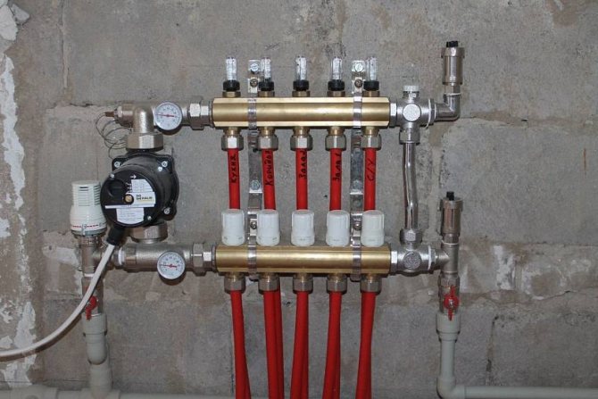
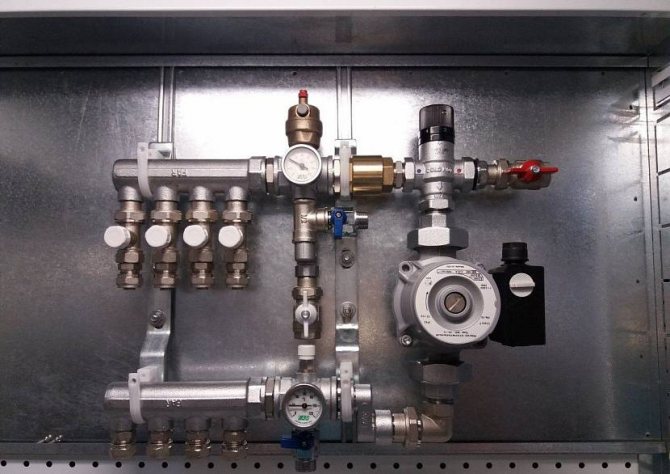
How does the manifold unit for underfloor heating with a pump work?

Manifold assembly - a system in which the cooled coolant is mixed with the liquid heated in the boiler, the temperature is equalized to a suitable level. The collector allows you to adjust the temperature of the coolant circulating in the circuits of the underfloor heating system. The liquid heated in the boiler enters the collector, and from it into the pipes under the floor, where, having given off part of the heat, the water cools down and returns back to the collector for mixing with the hotter supplied from the boiler.
The mixing process of the cooled and hot coolant is monitored using various sensors, valves, regulating drives.
To increase the efficiency of the collector warm floor, collectors with a pump are installed in the system, due to which the liquid circulates through the pipes forcibly.
The manifold assembly with a pump has several basic elements that ensure its smooth and efficient operation:
- Circulation pump. This unit is installed on the coolant supply pipeline and contributes to the active pumping of liquid along the circuits. The use of the pump makes it possible to increase the efficiency of the collector floor heating system several times.
- Mixing unit. Servo-driven valve that regulates the temperature of the heating medium. Having received a command from the temperature sensors to open or close the valve, the servo drive increases or decreases the supply of hot liquid to the collector, thereby achieving the desired temperature of the coolant.
- Distribution comb. A unit equipped with several outlets for the coolant, to which various circuits of the collector underfloor heating system are connected. A flow meter is installed on each circuit, which makes it possible to adjust the liquid temperature with special valves - manually or using automatic servo drives.
- Air vent. This device is mainly equipped with expensive, ready-made collector warm floor systems. Serves as an air vent to remove air that has entered the system.
- Meteorological sensor. A device that allows automatic adjustment of the collector floor system depending on weather conditions and temperature outside the window.


What are the sizes of boxes and options in demand
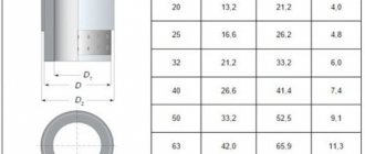
As a rule, constructions of the Grotto (Russia), Valtek (Italy), Vester (Russia) brands are most often bought. The sizes of the cabinets are different (see tables).
Dimensions of built-in manifold cabinets.
| Designation | Dimensions (edit) | Manufacturer |
| ShV-1 | 670×125×494 | Grota |
| ShV-1 | 648-711×120-180×450 | Wester |
| ShV-2 | 670×124×594 | Grota |
| ShV-2 | 648-711×120-180×550 | Wester |
| ShV-3 | 670×125×744 | Grota |
| ShV-3 | 648-711×120-180×700 | Wester |
| ShV-4 | 670×125×894 | Grota |
| ShV-4 | 648-711×120-180×850 | Wester |
| ShV-5 | 670×125×1044 | Grota |
| ShV-5 | 648-711×120-180×1000 | Wester |
| ShV-6 | 670×125×1194 | Grota |
| ShV-6 | 648-711×120-180×1150 | Wester |
| ShV-7 | 670×125×1344 | Grota |
Dimensions of external manifold cabinets.
| Designation | Dimensions (edit) | Manufacturer |
| SHN-1 | 651-691×120×454 | Grota |
| SHN-1 | 652-715×118×450 | Wester |
| SHN-2 | 651-691×120×554 | Grota |
| SHN-2 | 652-715×118×550 | Wester |
| SHN-3 | 651-691×120×704 | Grota |
| SHN-3 | 652-715×118×697 | Wester |
| SHN-4 | 651-691×120×854 | Grota |
| SHN-4 | 652-715×118×848 | Wester |
| SHN-5 | 651-691×120×1004 | Grota |
| SHN-5 | 652-715×118×998 | Wester |
| SHN-6 | 651-691×120×1154 | Grota |
| SHN-6 | 652-715×118×1147 | Wester |
| SHN-7 | 651-691×120×1304 | Grota |
| Shn-7 | 652-715×118×1300 | Wester |
After the system is installed, the branches are adjusted, it is required to perform a start-up, heating the heating structure in order to identify problems at an early date. In addition, experts advise specifically to create a working pressure in the system about 25% higher than during normal use, and pay attention to the tightness of the joints.
Installation nuances
When choosing the exact location of the manifold cabinet, it is worth consulting with professionals. Errors at this stage are fraught with excessive consumption of pipes or deviation of the pressure indicators in the heating system from the optimal value. The best results are obtained when the cabinet is installed at the midpoint of the room, near the floor surface. Special requirements are put forward for the flatness of the working base. Structures holding the manifold cabinet must not be level skewed.
The mounting pattern depends on the type of cabinet. Built-in models are installed after marking and laying the strobes with the obligatory fixing of the anchors on the outer sides of the box. After installing the collector, the heating circuit is finally closed and its tightness is checked. In the absence of leaks or pressure drops, possible gaps between the cabinet and the walls are covered with mortar or putty.
Types and characteristics of telecommunication cabinets, selection criteria
Wall-mounted varieties are mounted much easier. The anchor points are marked on the walls, the cabinet box is fixed with screws. By analogy with built-in models, a test run of heating becomes possible after the end of installation. Regardless of the type of construction chosen, when placing the collector inside the cabinet, remember the need to ensure maximum tightness of the connections, protect control devices... A detailed installation diagram, drawn up in advance, taking into account the dimensions, features of the cabinet and the location of communications, helps to avoid mistakes.
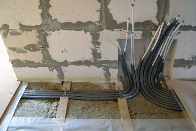
Prepare the attachment point according to the diagram
Install the cabinet, connect the heating system and check it, cover up any gaps between the wall and the cabinet